Model UT90C: OPERATING MANUAL Table of Contents Title Overview Unpacking Inspection Safety Information Rules For Safe Operation International Electrical Symbols The Meter Structure Rotary Switch Functional Buttons Display Symbols Measurement Operation A. AC & DC Voltage Measurement B. Measuring Resistance, Diodes, Continuity & Capacitance C. Frequency Measurement D. AC & DC Current Measurement E.
Model UT90C: OPERATING MANUAL Title Maintenance A. General Service B.
Model UT90C: OPERATING MANUAL Overview This Operating Manual covers information on safety and cautions. Please read the relevant information carefully and observe all the Warnings and Notes strictly. Warning To avoid electric shock or personal injury, read the “Safety Information” and “Rules for Safe Operation” carefully before using the Meter.
Model UT90C: OPERATING MANUAL Unpacking Inspection Open the package case and take out the Meter. Check the following items carefully to see any missing or damaged part: Item 1 2 3 Description English Operating Manual Test Lead Holster Qty 1 piece 1 pair 1 piece In the event you find any missing or damage, please contact your dealer immediately.
Model UT90C: OPERATING MANUAL Safety Information Safety Information This Meter complies with standards IEC61010: in pollution degree 2, overvoltage category (CAT. II 1000V, CAT. III 600V) and double insulation. Use the Meter only as specified in this operating manual, otherwise the protection provided by the Meter may be impaired. In this manual, a Warning identifies conditions and actions that pose hazards to the user, or may damage the Meter or the equipment under test.
Model UT90C: OPERATING MANUAL Rules For Safe Operation (1) To avoid possible electric shock or personal injury, and to avoid possible damage to the Meter or to the equipment under test, adhere to the following rules: l Before using the Meter inspect the case. Do not use the Meter if it is damaged or the case (or part of the case) is removed. Look for cracks or missing plastic. Pay attention to the insulation around the connectors. l Inspect the test leads for damaged insulation or exposed metal.
Model UT90C: OPERATING MANUAL Rules For Safe Operation (2) l l l l l l produce false readings that can lead to electric shock and personal injury. When servicing the Meter, use only the same model number or identical electrical specifications replacement parts. The internal circuit of the Meter shall not be altered at will to avoid damage of the Meter and any accident. Soft cloth and mild detergent should be used to clean the surface of the Meter when servicing.
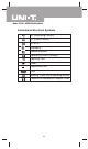
Model UT90C: OPERATING MANUAL International Electrical Symbols AC (Alternating Current). DC (Direct Current). AC or DC. Grounding. Double Insulated. Deficiency of Built-In Battery. Continuity Test. Diode. Capacitance Test Fuse. Warning. Refer to the Operating Manual. Conforms to Standards of European Union.
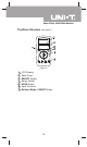
Model UT90C: OPERATING MANUAL The Meter Structure (see figure 1) ( figure 1) 1 2 3 4 5 6 7 LCD Display. Solar Panel. SELECT Button. Rotary Switch. HOLD Button.
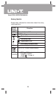
Model UT90C: OPERATING MANUAL Rotary Switch Below table indicated for information about the rotary switch positions. Rotary Function Switch Position OFF Power is turned off. AC/DC voltage measurement. : Diode test. : Continuity test. : Capacitance test. Ω Hz Ω : Resistance measurement. Frequency Test. AC or DC Current Measurement l CHARGE 230V MAX: Charge at 220VAC. l 12-36V : Charge at 12-36V .
Model UT90C: OPERATING MANUAL Functional Buttons Below table indicated for information about the functional button operations. Button Measuring Function Operation Performed Any rotary RESET switch position except Hz and CHARGE Press RESET to enter and exit the mode in any measuring mode except in frequency and charge mode; the Meter beeps. Switches between AC and DC voltage/current; the Meter beeps. DC is default.
Model UT90C: OPERATING MANUAL Display Symbols(1) (see figure 2) ( figure 2) No. Symbol 1 AC 2 3 Indicator for AC voltage or current. The displayed value is the mean value. Indicates negative reading. CHARGE Charge indicator. The Meter is in the auto range mode in which the Meter automatically selects the range with the best resolution. 4 5 Data hold is active. The mode on,which display the present value minus the stored value. 6 The battery is low.
Model UT90C: OPERATING MANUAL Display Symbols(2) (see figure 2) No. Symbol 11 Meaning The continuity buzzer is on. 9 10 Test of diode. Ω: Ohm. The unit of resistance. Ω,kΩ,MΩ kΩ: kilohm.1 x 103 or 1000 ohms. MΩ: Megaohm. 1 x 10⁶ or 1,000,000 ohms. F: Farad. The unit of capacitance. µF, nF µF: Microfarad. 1 x 10⁻⁶ or 0.000001 farads. nF: Nanofarad. 1 x 10⁻⁹ or 0.000000001 farads. Hz: Hertz.The unit of frequency Hz, in cycles/second. kHz, kHz: Kilohertz. 1 x 10³ or 1,000 MHz hertz. MHz: Megahertz.
Model UT90C: OPERATING MANUAL Measurement Operation(1) A.DC & AC Voltage Measurement (see figure 3) red black ( figure 3) Warning To avoid harms to you or damages to the Meter from electric shock, please do not attempt to measure voltages higher than 1000VDC / 750VAC RMS although readings may be obtained. AC voltage measurement The AC voltage ranges are: 4.000V, 40.00V, 400.0V and 750.0V. To measure AC Voltage, connect the Meter as follows: 1. 2. 3.
Model UT90C: OPERATING MANUAL Measurement Operation(2) Note l At 400mV range, the Meter has an input impedance of 4000MΩ All other ranges the Meter has an input impedance of 10MΩ This loading effect can cause measurement errors in high impedance circuits. If the circuit impedance is less than or equal to 10kΩ, the error is negligible (0.1% or less). l When AC voltage measurement has been completed, disconnect the connection between the testing leads and the circuit under test.
Model UT90C: OPERATING MANUAL Measurement Operation(3) B.Measuring Resistance, Diodes, Continuity & Capacitance Warning To avoid harms to you, never attempt to input over 60V in DC or 30V rms in AC. To avoid damages to the Meter or to the devices under test, disconnect circuit power and discharge all the high-voltage capacitors before measuring resistance, diodes, continuity & capacitance For testing capacitance, use the DC Voltage function to confirm that the capacitor is discharged.
Model UT90C: OPERATING MANUAL Measurement Operation(4) 2. Set the rotary switch toΩ , resistance measurement (Ω) is defaults or press SELECT button to select Ω measurement mode. 3. Connect the test leads across with the object being measured. The measured value shows on the display. Note l The test leads can add 0.1Ωto 0.2Ωof error to resistance measurement. To obtain precision readings in low-resistance measurement, that is the range of 400.
Model UT90C: OPERATING MANUAL Measurement Operation(5) Testing Diodes (see figure 5) red black ( figure 5) Use the diode test to check diodes, transistors, and other semiconductor devices. The diode test sends a current through the semiconductor junction, and then measures the voltage drop across the junction. A good silicon junction drops between 0.5V and 0.8V. To test a diode out of a circuit, connect the Meter as follows: 1.
Model UT90C: OPERATING MANUAL Measurement Operation(6) l l Connect the test leads to the proper terminals as said above to avoid error display. The LCD will display OL indicating open-circuit for wrong connection. The unit of diode is Volt (V), displaying the positiveconnection voltage-drop value. When diode testing has been completed, disconnect the connection between the testing leads and the circuit under test.
Model UT90C: OPERATING MANUAL Measurement Operation(7) l When continuity testing has been completed, disconnect the connection between the testing leads and the circuit under test. Capacitance Measurement (see figure 7) red black ( figure 7) The Meter’s capacitance ranges are: 40.00nF, 400.0nF, 4.000µF, 40.00µF, and 100.0µF. To measure capacitance, connect the Meter as follows: 1. Insert the red test lead into the HzVΩ terminal and the black test lead into the COM terminal. 2.
Model UT90C: OPERATING MANUAL Measurement Operation(8) l For testing the capacitor with polarity, connect the red test lead to anode & black test lead to cathode instead of using test leads as mentioned above. l It takes a longer time when testing a capacitor value which is higher than 10µF range. l When capacitance measurement has been completed, disconnect the connection between the testing leads and the circuit under test. C.
Model UT90C: OPERATING MANUAL Measurement Operation(9) Note l When Hz measurement has been completed, disconnect the connection between the testing leads and the circuit under test. D.AC & DC Current Measurement (see figure 9) black red ( figure 8) Warning Never attempt an in-circuit current measurement where the open-circuit voltage between the circuit and ground is greater than 60V. If the fuse burns out during measurement, the Meter may be damaged or the operator himself may be hurt.
Model UT90C: OPERATING MANUAL Measurement Operation(10) To measure current, do the following: 1. Turn off power to the circuit. Discharge all highvoltage capacitors. 2. Insert the red test lead into theµAmA or 10A terminal and the black test lead into the COM terminal. Use the 10A terminal and A range if the current value to be tested is an unknown. 3. Set the rotary switch to µA , mA orA . 4. The Meter defaults to DC current measurement mode.
Model UT90C: OPERATING MANUAL Measurement Operation(11) E.Power Charging (see figure 10) red black ( figure 10) Warning Start charging as soon as the power indicator appears. With a low battery, the Meter might produce false readings that can lead to electric shock and personal injury. To avoid damage to the Meter, please do not attempt to changeover the rotary switch during charging. To set up charging as follows: l Charge at 220V AC 1.
Model UT90C: OPERATING MANUAL Measurement Operation(11) l Charge at 12-36V 1. Insert the red test lead into the HzVΩ erminal and the black test lead into the COM terminal. 2. Set the rotary switch to 12-36V . 3. Place the test leads’ probe tip onto the 12-36V power supply respectively. 4. CHARGE shows on the display. 5. The charging time is more than 30 mins. 6.
Model UT90C: OPERATING MANUAL Operation of Hold Mode Warning To avoid possibility of electric shock, do not use Hold mode to determine if circuits are without power. The Hold mode will not capture unstable or noisy readings. The Hold mode is applicable to all measurement functions. l Press to enter Hold mode; the Meter beeps. l Press again to exit Hold mode; the Meter beeps. l In Hold mode, is displayed.
Model UT90C: OPERATING MANUAL General Specifications(2) l Safety/Compliances l Certification : IEC61010: CAT. II 1000V, CAT. III 600V overvoltage and double insulation standard.
Model UT90C: OPERATING MANUAL Accuracy Specification(1) Accuracy: (a% reading + b digits),guarantee for 1 year. o o Operating temperature:23 C 5 C. Relative humidity:<75%. o Temperature coefficient: 0.1 x (specified accuracy) / 1 C. A.AC Voltage Range Resolution 4V 40V 400V 750V 1mV 10mV 100mV 1V Accuracy Overload Protection (1%+5) 1000V DC or 750V AC continuous. (1.2%+5) Remarks: l Input impedance: approx. 10MΩ. l Frequency response: 40Hz ~ 400Hz.
Model UT90C: OPERATING MANUAL Accuracy Specification(2) C. Resistance Range Resolution 400Ω 4kΩ 40kΩ 400kΩ 4MΩ 40MΩ 0.1Ω 1Ω 10Ω 100Ω 1kΩ 10kΩ Overload Protection Accuracy (1.2%+2) (1%+2) 600Vp (1.2%+2) (1.5%+2) Remarks: l Open circuit voltage: approx. 0.45V D. Diode & Continuity Range Resolution Overload Protection 1mV 600Vp 1Ω E.
Model UT90C: OPERATING MANUAL Maintenance(1) This section provides basic maintenance information including battery and fuse replacement instruction. Warning Do not attempt to repair or service your Meter unless you are qualified to do so and have the relevant calibration, performance test, and service information. To avoid electrical shock or damage to the Meter, do not get water inside the case. A. General Service l Periodically wipe the case with a damp cloth and mild detergent.
Model UT90C: OPERATING MANUAL Maintenance(2) Warning To avoid electrical shock or arc blast, or personal injury or damage to the Meter, use specified fuses ONLY in accordance with the following procedure. Replacement of the fuses is seldom required. Burning of a fuse always results from improper operation. ** END ** This operating manual is subject to change without notice.
Model UT90C: OPERATING MANUAL Copyright 2001 Uni-Trend International Limited. All rights reserved. Manufacturer: UNI-TREND TECHNOLOGY(DONG GUAN)LIMITED Address: Dong Fang Da Dao, Bei Shan Dong Fang Industrial Development District, Hu Men Town, Dong Guan City, Guang Dong Province, China Headquarters: Uni-Trend International Limited Address: Rm901, 9/F, Nanyang Plaza 57 Hung To Road Kwun Tong Kowloon, Hong Kong Tel: (852) 2950 9168 Fax: (852) 2950 9303 Email: info@uni-trend.com http://www.uni-trend.