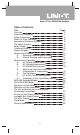
Model UT70C: OPERATING MANUAL Table of Contents Title Overview Unpacking Inspection Safety Information Rules For Safe Operation International Electrical Symbols The Meter Structure Rotary Switch Functional Buttons Display Symbols Measurement Ranges A. Selecting a Measurement Range B. Manual Ranging and Autoranging Measurement Operation A. AC Voltage Measurement B. DC Voltage Measurement C. DC Milivolt Measurement D. Measuring Continuity, Resistance, Conductance & Capacitance E. Testing Diodes F.
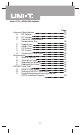
Model UT70C: OPERATING MANUAL Accuracy Specifications A. AC Voltage B. DC Voltage C. Continuity, Resistance & Conductance Test D. Capacitance Diodes Test E. F. DC Current G. AC Current H. Frequency & Duty Cycle Maintenance A. General Service B. Testing the Fuses C. Replacing the Battery D. Replacing the Fuses RS232C Serial Port A. RS232C Port Cable B. Setting of RS232C Serial Ports C.
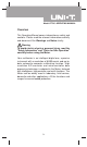
Model UT70C: OPERATING MANUAL Overview This Operating Manual covers information on safety and cautions. Please read the relevant information carefully and observe all the Warnings and Notes strictly. Warning To avoid electric shock or personal injury, read the "Safety Information" and "Rules for Safe Operation" carefully before using the Meter. Your multimeter is an intelligent digital one, a precise instrument with a resolution of 8,000 counts and up-todate automatic computer calibrating function.
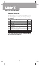
Model UT70C: OPERATING MANUAL Unpacking Inspection Open the package case and take out the Meter.
Model UT70C: OPERATING MANUAL Safety Information CE Version: The Meter complies with the standards IEC61010-1:in pollution degree 2, overvoltage category CAT III 1000V, CAT IV 600V and double insulation . UL Version: The Meter complies with the standards UL61010B-1, in pollution degree 2, overvoltage category CAT II 1000V and double insulation. CAT. II: Local level, appliance, PORTABLE EQUIPMENT etc., with smaller transient voltage overvoltages than CAT. III CAT.
Model UT70C: OPERATING MANUAL Rules For Safe Operation (1) Warning To avoid possible electric shock or personal injury, and to avoid possible damage to the Meter or to the equipment under test, adhere to the following rules: l l l l l l l l Before using the Meter inspect the case. Do not use the Meter if it is damaged or the case (or part of the case) is removed. Look for cracks or missing plastic. Pay attention to the insulation around the connectors.
Model UT70C: OPERATING MANUAL Rules For Safe Operation (2) l Disconnect circuit power and discharge all highvoltage capacitors before testing resistance, conductance, continuity, diodes, current, or capacitance. l Before measuring current, check the Meter's fuses and turn off power to the circuit before connecting the Meter to the circuit. l Replace the battery as soon as the battery indicator appears.
Model UT70C: OPERATING MANUAL International Electrical Symbols AC (Alternating Current) DC (Direct Current) AC or DC Grounding Double Insulated Deficiency of Built-In Battery Continuity Test Diode Capacitance Test Fuse Warning.
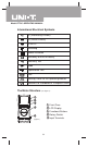
Model UT70C: OPERATING MANUAL Rotary Switch Below table indicated for information about the rotary switch positions. Rotary Switch Position OFF V V mV A mA Function Power is turned off. AC voltage measurement. DC voltage measurement. DC millivolt measurement. : Continuity test. : Resistance measurement. : Capacitance test. Diode Test. AC or DC Current Measurement from 0.001A to 10.00A . AC or DC Current Measurement from 0.1mA to 800.0mA.
Model UT70C: OPERATING MANUAL Functional Buttons (1) Below table indicated for information about the functional button operations. Button Measuring Operation Performed Function Continuity Turn the continuity buzzer on and Test off in resistance measurement mode. At OFF Press while turning on the position Meter to disable the beeper at all functions except short circuit and diode testing.
Model UT70C: OPERATING MANUAL Functional Buttons (2) HOLD Any rotary switch position Conductance mode A , mA REL Hz At OFF position Any rotary switch position Press HOLD to enter and exit the Hold mode in any mode; the Meter beeps. Press HOLD to toggle between conductance and resistance value. Present resistance value is kept. Press to select capacitance test. Press to select DC or AC current. DC is default. To disable the Sleep Mode, press while turning on the Meter.
Model UT70C: OPERATING MANUAL Display Symbols (1) (see figure 2) (figure 2) No. Symbol 3 Meaning The Meter is in the auto range mode in which the Meter automatically selects the range with the best resolution. The battery is low. Warning: To avoid false readings, which could lead to possible electric shock or personal injury, replace the battery as soon as the battery indicator appears. Indicates negative reading. 4 Test of diode. 1 2 5 6 7 8 9 10 11 The continuity buzzer is on.
Model UT70C: OPERATING MANUAL Display Symbols (2) 12 13 14 15 16 17 W:: , kW: K : k , M MW: M : Ohm. The unit of resistance. kilohm. 1 x 10³ or 1000 ohms. Megohm. 1 x 10⁶ or 1,000,000 ohms. Hz, kHz, Hz: Hertz. The unit of frequency. MHz kHz: Kilohertz. 1 x 10³ or 1000 hertz. MHz: Meghertz. 1 x 10⁶ or1,000,000 hertz. V, mV V: Volts. The unit of voltage. mV: Millivolt. 1 x 10⁻³ or 0.001 volts. A, mA A: Amperes (amps). The unit of current. mA: Milliamp. 1 x 10⁻³ or 0.001 amperes. F, F, nF F: Farad.
Model UT70C: OPERATING MANUAL Measurement Ranges (1) A measurement range determines the highest value the Meter can measure. Most Meter functions have more than one range. See "Accuracy Specifications." A. Selecting a Measurement Range Being in the right measurement range is important: l If the range is too low for the input, the Meter displays to indicate an overload. l If the range is too high, the Meter will not display the most accurate measurement. B.
Model UT70C: OPERATING MANUAL Measurement Ranges (2) 1. Press RANGE. The Meter enters the manual range mode and turns off. Each presses of RANGE increments the range. When the highest range is reached, the Meter wraps to the lowest range. 2. To exit the manual range mode, press and hold RANGE for over one second. The Meter returns to the autorange mode and is displayed. Note l In Hold and MAX MIN mode, press RANGE exits these measurement modes and enters manual range mode.
Model UT70C: OPERATING MANUAL Measurement Operation (1) A. AC Voltage Measurement (see figure 3) red black (figure 3) Warning To avoid harms to you or damages to the Meter from electric shock, please do not attempt to measure voltages higher than 1000V / 750V rms although readings may be obtained. The AC Voltage ranges are: 800.0mV, 8.000V, 80.00V, 800.0V and 1000V. To measure AC Voltage, connect the Meter as follows: 1. 2. 3.
Model UT70C: OPERATING MANUAL Measurement Operation (2) B. DC Voltage Measurement (see figure 4) red black (figure 4) Warning To avoid harms to you or damages to the Meter from electric shock, please do not attempt to measure voltages higher than 1000V / 750V rms although readings may be obtained. The DC Voltage ranges are: 8.000V, 80.00V, 800.0V and 1000V. To measure DC Voltage, connect the Meter as follows: 1. 2. 3.
Model UT70C: OPERATING MANUAL Measurement Operation (3) C. DC Millivolt Measurement (see figure 5) red black (figure 5) Warning To avoid harms to you or damages to the Meter from electric shock, please do not attempt to measure voltages higher than 1000V / 750V rms although readings may be obtained. The DC Millivolt ranges are: 80.00mV and 800.0mV. These ranges have more than 4000M . To measure DC Millivolt, connect the Meter as follows: 1. 2. 3.
Model UT70C: OPERATING MANUAL Measurement Operation (4) D. Measuring Continuity, Resistance, Conductance & Capacitance Warning To avoid damages to the Meter or to the devices under test, disconnect circuit power and discharge all the high-voltage capacitors before measuring continuity, resistance, conductance and capacitance. When measuring capacitance, use the DC Voltage function to confirm that the capacitor is discharged.
Model UT70C: OPERATING MANUAL Measurement Operation (5) Resistance Measurement (see figure 7) Select W Test red black (figure 7) The resistance ranges are: 800.0 , 8.000k , 80.00k , 800.0k , 8.000M and 80.00M . To measure resistance, connect the Meter as follows: 1. 2. 3. Insert the red test lead into the V Hz terminal and the black test lead into the COM terminal. Set the rotary switch to , resistance measurement is default or press to select measurement mode.
Model UT70C: OPERATING MANUAL Measurement Operation (6) l The LCD displays indicating open-circuit for the tested resistor or the resistor value is higher than the maximum range of the Meter. l When resistance measurement has been completed, disconnect the connection between the testing leads and the circuit under test. Conductance Measurement (see figure 8) Select nS Test red black (figure 8) The resistance ranges from 0.01nS to 80nS. To measure conductance, connect the Meter as follows: 1. 2. 3.
Model UT70C: OPERATING MANUAL Measurement Operation (7) Capacitance Measurement (see figure 9) Select nF Test red black (figure 9) The Meter's capacitance ranges are: 1.000nF, 10.00nF, 100.0nF, 1.000 F, 10.00 F and 100.0 F. To measure capacitance, connect the Meter as follows: 1. 2. 3. Insert the red test lead or the red test clip into the V Hz terminal and the black test lead or black test clip into the COM terminal. Set the rotary switch to and press to select nF measurement mode.
Model UT70C: OPERATING MANUAL Measurement Operation (8) E. Testing Diodes (see figure 10) red black (figure 10) Warning To avoid possible damage to the Meter and to the device under test, disconnect circuit power and discharge all high-voltage capacitors before testing diodes. Use the diode test to check diodes, transistors, and other semiconductor devices. The diode test sends a current through the semiconductor junction, then measures the voltage drop across the junction.
Model UT70C: OPERATING MANUAL Measurement Operation (9) Note l In a circuit, a good diode should still produce a forward voltage drop reading of 0.5V to 0.8V; however, the reverse voltage drop reading can vary depending on the resistance of other pathways between the probe tips. l Connect the test leads to the proper terminals as said above to avoid error display. l The LCD will display indicating open-circuit for wrong connection.
Model UT70C: OPERATING MANUAL Measurement Operation (10) The current measurement has 2 measurement positions on the rotary switch: A and mA . The A has a 8.000A and 10.00A range, with auto ranging; the mA has a 80.00mA and 800.0mA range, with auto ranging. To measure current, do the following: 1. Turn off power to the circuit. Discharge all highvoltage capacitors. 2. Insert the red test lead into the A or mA or terminal and the black test lead into the COM terminal. 3. Set the rotary switch to A or mA .
Model UT70C: OPERATING MANUAL Measurement Operation (11) G. Frequency & Duty Cycle Measurement (see figure 12) Select Hz or Duty Cycle Test red black (figure 12) Frequency Measurement The measurement ranges are: 1kHz, 10kHz, 100kHz and 1MHz. The maximum measurement range is 1MHz. To measure frequency, connect the Meter as follows: 1. 2. 3. 4. Insert the red test lead into the V Hz terminal and the black test lead into the COM terminal.
Model UT70C: OPERATING MANUAL Measurement Operation (12) Duty Cycle Measurement The duty cycle measurement range is 0.01% ~ 99.99%. To measure duty cycle: 1. Set up the Meter to measure frequency. 2. To select duty cycle, press Hz again (or until the % symbol is shown on the display). 3. Connect the test leads across with the object being measured. The measured value shows on the display. Note l It is recommended to use mV range. l The polarity of trigger slope is positive.
Model UT70C: OPERATING MANUAL MAX MIN Recording Mode (1) (see figure 13) Select MAX, MIN, AVG or Present value red black (figure 13) MAX MIN recording mode applies to all measurement functions except at conductance measurement function. MAX MIN recording mode captures and stores the maximum and minimum input value detected, and calculates a running average of all readings taken.
Model UT70C: OPERATING MANUAL MAX MIN Recording Mode (2) MAX MIN Function To enter the MAX MIN mode. 1. To exit the MAX MIN mode. Press MAX MIN for over 1 second. The Meter exists MAX MIN. Recorded values are erased and the Meter stays in the selected range. Action Make sure that the Meter is in the desired measurement function and range. 2. Press MAX MIN to enter MAX MIN recording mode. The present reading is displayed, and the Meter is locked in the present range, and REC is displayed. 3.
Model UT70C: OPERATING MANUAL PEAK MAX MIN Mode (see figure 14) Select MAX or MIN Select 1ms response time red black (figure 14) PEAK MAX MIN mode is an additional function of . Pressing to toggle between 100ms response time and 1ms response time. This function can only be enabled when the Meter is under REC mode or REC mode plus Hold mode except at mode. To enter PEAK MAX MIN mode: l Press MAX MIN or MAX MIN and HOLD to enter REC mode.
Model UT70C: OPERATING MANUAL Operation of Hold Mode Warning To avoid possibility of electric shock, do not use Hold mode to determine if circuits are without power. The Hold mode will not capture unstable or noisy readings. The Hold mode is applicable to all measurement functions. With the Auto Hold function, it automatically holds the present reading on the display, freeing you to concentrate on the placement of the test leads when working in dangerous or difficult situations.
Model UT70C: OPERATING MANUAL Operation of Auto Hold Mode Auto Hold means you no need to press HOLD, the readings on the LCD will be hold automatically. Conditions to enter Auto Hold Mode: l When input signal is larger than AC/DC 100mV, Auto Hold mode will be enabled automatically. l When the change of signal three times continuously within 3 digits, it will hold the last value; the Meter beeps. l Considers every value as the base value.
Model UT70C: OPERATING MANUAL The Use of Relative Value and Relative Percentage Value Mode The and % mode applies to all measurement functions, with auto ranging. REL mode can be used together with Auto Hold and MAX MIN mode. The definition is as follows: l Relative value ( ) = present value - stored value For instance, if the stored value is 20.0V and the present value is 22.0V, the reading would be 2.0V. If a new measurement value is equal to the stored value then display 0.0V.
Model UT70C: OPERATING MANUAL Turning on the Display Backlight Warning In order to avoid the hazard arising from mistaken readings in insufficient light or poor vision, please use the Display Backlight function. l l Press to turn on the Display Backlight and it will automatically off after about 60 seconds. Press and hold for about 2 seconds to turn the Display Backlight off. Analogue Bar Graph Display The analogue bar graph likes the needle in a traditional analogue meter (AMM).
Model UT70C: OPERATING MANUAL Full Icons Display If the Meter is turned on with any functional button being pressed on, the LCD will display all the icons and maintain this mode until the button is released 3 seconds later. Sleep Mode l To preserve battery life, the Meter automatically turns off if you do not turn the rotary switch or press any button for about 30 minutes. The buzzer beeps three times 5 minutes before turning off.
Model UT70C: OPERATING MANUAL General Specifications l Maximum Voltage between :1000V rms. any Terminals and Grounding :1A,250V fast type glass l fuse, 5x20mm. l l :10A,250V fast type glass fuse, 5x20mm. :8000, updates 5 times /second. o o :Operating:5 C~40 C l Temperature o o (41 F ~104 F). o o Storage:-10 C~50 C o o (14 F~122 F). o o :<80% @ 5 C - 31 C; l Relative Humidity o o <50% @ 31 C - 40 C. :Operating: 2000 m. l Altitude Storage: 10000 m. :One piece of 9V l Battery Type NEDA1604 or 6F22 or 006P.
Model UT70C: OPERATING MANUAL Accuracy Specifications (1) Accuracy: (a% reading + b digits), guarantee for 1 year. o o Operating temperature: 23 C 5 C. Relative humidity: <80%. o Temperature coefficient: 0.1 x (specified accuracy) / 1 C A. AC Voltage Range Resolution Accuracy 50Hz~60Hz 40Hz~400Hz (1.5%+4) 800mV 100 V 8V 1mV (1%+3) (1.5%+3) 80V 10mV 800V 100mV (2.5%+4) 1000V 1V Overload Protection: AC/DC: 1000V rms Remarks: l Input impedance: 10M .
Model UT70C: OPERATING MANUAL Accuracy Specifications (2) C. Continuity, Resistance & Conductance Test Overload Range Resolution Accuracy Protection Continuity Test 0.1 Approximate (800.0 ) 100 800 0.1 (0.5%+3) 8k 1 80k 10 (0.5%+1) 500V rms 800k 100 8M 1k 80M 10k (2%+3) Conductance Test 0.01nS (2%+10) (80nS) Remarks: l Continuity Test (800.0 ): Buzzer beeps continuously. Open circuit voltage approximate 0.7V. l At 800 ~ 80M Range: Open circuit voltage approximate 0.7V.
Model UT70C: OPERATING MANUAL Accuracy Specifications (3) F. DC Current Range Resolution Accuracy 80mA 10 A 800mA 100 A 8A 1mA 10A 10mA Overload Protection 1A,250V fast type glass fuse, 5x20mm. (0.3%+2) 10A,250V fast type glass fuse, 5x20mm. Remark: l At 8A & 10A Range: For continuous measurement 10 seconds and interval time between 2 measurements greater than 15 minutes. G.
Model UT70C: OPERATING MANUAL Accuracy Specifications (4) H. Frequency & Duty Cycle Frequency - At mV Range Range Resolution Accuracy 1kHz 0.01Hz 10kHz 0.1Hz (0.02%+1) 100kHz 1Hz 1MHz 10Hz Remarks: l Input sensitivity as follows: <100kHz: 100mV rms; 100kHz: 500mV rms; l Maximum input amplitude: 30V rms. Frequency - At V &V Overload Protection 500V rms Range Range Accuracy Overload Protection 10Hz~100kHz (0.1%+3) 1000V Remarks: l Input amplitude: 500mV rms. l Maximum input amplitude: 30V rms.
Model UT70C: OPERATING MANUAL Accuracy Specifications (5) Remarks: l Reading is only for reference purpose. l At mV 8V Range: Positive pulse width 30 s. Maintenance (1) This section provides basic maintenance information including battery and fuse replacement instruction. Warning Do not attempt to repair or service your Meter unless you are qualified to do so and have the relevant calibration, performance test, and service information.
Model UT70C: OPERATING MANUAL Maintenance (2) B. Testing the Fuses Warning To avoid electrical shock or personal injury, remove the test leads and any input signals before replacing the battery or fuse. To prevent damage or injury, install ONLY replacement fuses with identical amperage, voltage, and speed ratings. To test the fuse: 1. 2. Set the rotary switch to and select by pressing . Plug a test lead into the terminal V Hz and touch the probe tip to the 10A or mA terminal.
Model UT70C: OPERATING MANUAL Maintenance (3) C. Replacing the Battery (see figure 15) Holster The Meter (figure 15) Warning To avoid false readings, which could lead to possible electric shock or personal injury, replace the battery as soon as the battery indicator " " appears. To replace the battery: 1. 2. 3. 4. 5. 6. Turn the Meter to OFF position and remove all connections from the terminals. Take out the Meter from the holster.
Model UT70C: OPERATING MANUAL Maintenance (4) D. Replacing the Fuses (see figure 15) Warning To avoid electrical shock or arc blast, or personal injury or damage to the Meter, use specified fuses ONLY in accordance with the following procedure. To replace the Meter's fuse: 1. 2. 3. 4. 5. 6. 7. 8. Turn the Meter to OFF position and remove all connections from the terminals. Take out the Meter from the holster.
Model UT70C: OPERATING MANUAL RS232C Serial Port (1) A. RS232C Port Cable The Computer Meter D-sub D-sub D-sub 9 Pin 25 Pin Pin Remark 9 Pin Male FemaleFemale Name 2 3 4 5 6 7 8 B.
Model UT70C: OPERATING MANUAL RS232C Serial Port (2) C. System Requirements for Installing the UT70C Interface Program To use UT70C Interface Program, you need the following hardware and software: l An IBM PC or equivalent computer with 80586 or higher processor and 640 x 480 pixel or better monitor. l Microsoft Windows 95 or above. l At least 16 MB of RAM. l At least 8MB free space in hard drive. l Can access to a local or a network CD-ROM. l A free serial port.
Model UT70C: OPERATING MANUAL 47
Model UT70C: OPERATING MANUAL Copyright 2001 Uni-Trend International Limited. All rights reserved. Manufacturer: UNI-TREND TECHNOLOGY(DONG GUAN)LIMITED Address: Dong Fang Da Dao, Bei Shan Dong Fang Industrial Development District, Hu Men Town, Dong Guan City, Guang Dong Province, China Headquarters: Uni-Trend International Limited Address: Rm901, 9/F, Nanyang Plaza 57 Hung To Road Kwun Tong Kowloon, Hong Kong Tel: (852) 2950 9168 Fax: (852) 2950 9303 Email: info@uni-trend.com http://www.uni-trend.