
Specifications


info@tursdaletechnicalservices.co.uk
7
3. Connect the test clips across with the object being measured.
The measured value shows on the display.
Note
When measuring at 20Ω and 200Ω range, the test clips can add 0.1 to 0.3 error to resistance. To obtain
precise readings in these low-resistance measurement, that is the range 20Ω and 200Ω, short circuit the
input terminals before hand and record the reading obtained (called this reading as X). (X) is the
additional resistance from the test clips.
Then use the equation:
measured resistance value (Y) – (X) = precision readings of resistance.
The Meter displays “1” when there is no input, for example, open circuit situation.
For high resistance measurement (>1M), it is normal taking several seconds to obtain a stable reading.
When resistance measurement has been completed, disconnect the connection between the testing clips
and the circuit under test and remove the testing clips away from the input terminals of the Meter.
B. Diode and Continuity Test
Warning
To avoid damages to the Meter or to the devices under test, disconnect circuit power and discharge all
the high-voltage capacitors before measuring diodes and continuity. Do not input more than DC 60V or
AC 30V voltages to avoid electric shock and damage to the Meter.
Testing Diodes
Use the diode test to check diodes, transistors, and other semiconductor devices. The diode test sends a
current through the semiconductor junction, and then measures the voltage drop across the junction. A
good silicon junction drops between 500mV and 800mV.
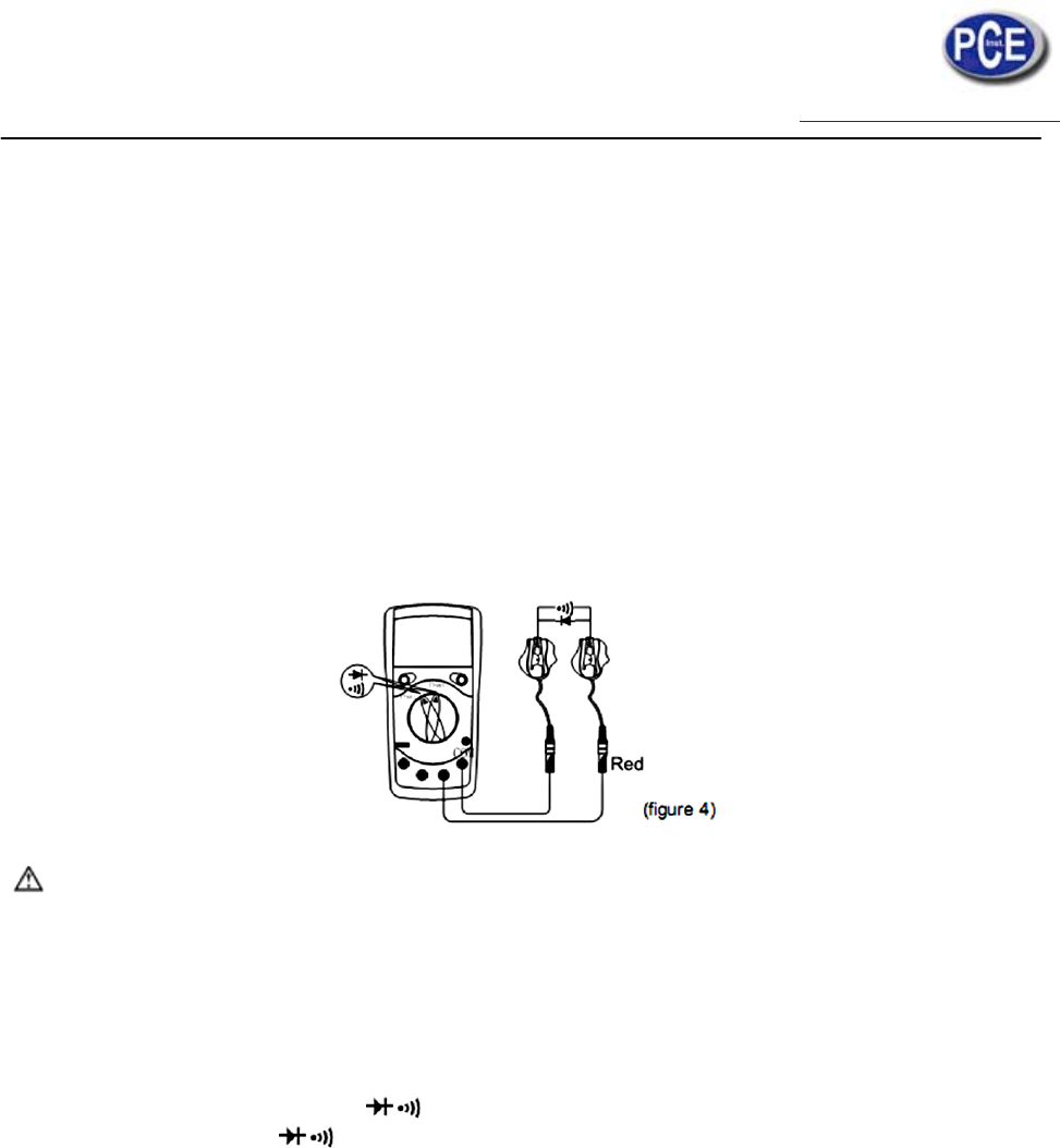
To test a diode out of a circuit, connect the Meter as follows:
1. Insert the red test clip into the Ω
terminal and the black test clip into the COM terminal.
2. Set the rotary switch to
.
3. For forward voltage drop readings on any semiconductor component, place the red test clip on the
component’s anode and place the black test clip on the component’s cathode.
The display shows the diode forward voltage drop’s nearest value.
Note
- In a circuit, a good diode should still produce a forward voltage drop reading of 500mV to 800mV;
however, the reverse voltage drop reading can vary depending on the resistance of other pathways
between the probe tips.
- Connect the test clips to the proper terminals as said above to avoid error display. The LCD will
display “1” indicating open-circuit for wrong connection. The unit of diode is Volt (V), displaying the
positive-connection voltage-drop value.
- When diode test has been completed, disconnect the connection between the testing clips and the
circuit under test and remove the testing clips away from the input terminals of the Meter.
Testing for Continuity