
Specifications


AD Instruments
_______________________________________________________________________________
©Copyright Abacanto Digital SA. 23
Manual de usuario AD511
l Don’t touch the test leads even after it has been removed from the circuit until voltages are all released.
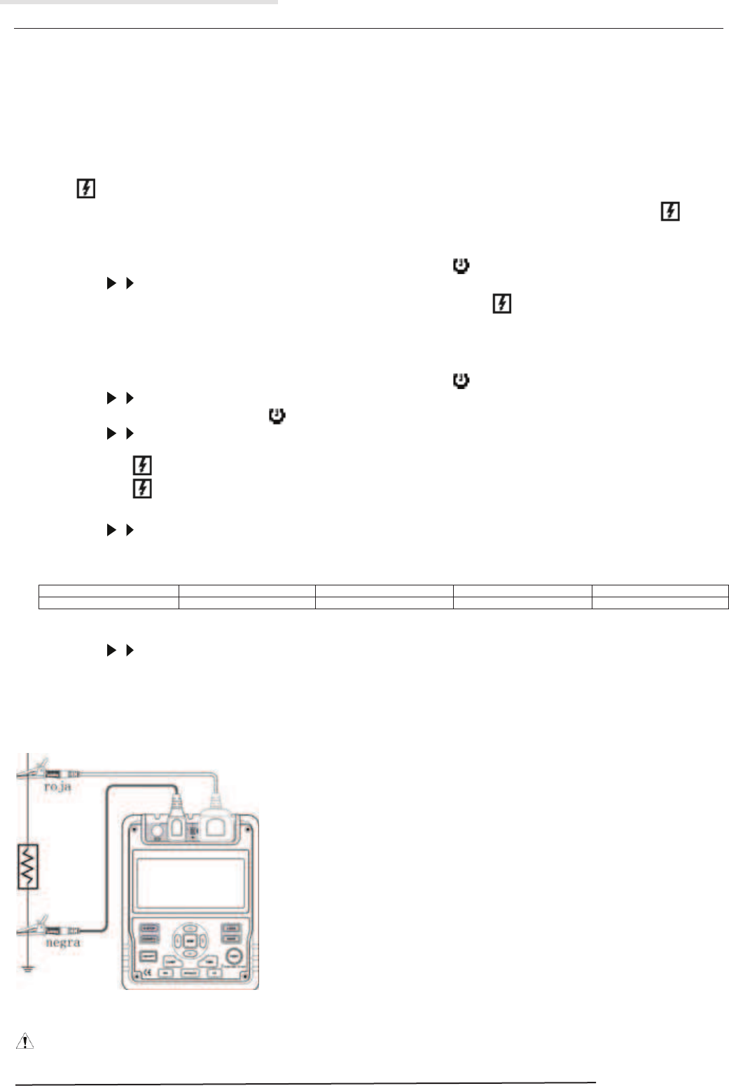
To measure insulation resistance, set up the Meter as Figure 5 and do the following:
6. Press HO button to select insulation resistance measurement.
7. Press Ʒ and ͩ button to select voltages of 100V, 250V, 500V or 1000V.
8. Insert the red test lead into the LINE terminal and the black test lead into EARTH terminal.
9. Connect the red and black alligator clip to the circuit to be measured, positive voltage output from LINE terminal.
10. Choose below insulation resistance measurement mode.
a) Continuous Measurement
l Press TIME button to select continuous measurement mode, there is no timer icon on the LCD.
l Press and hold TEST button for 1 second to carry out continuous measurement. Output insulation resistance testing voltage, TEST button light up,
blinks on every 0.5 seconds.
l Press TEST button to close the insulation resistance measurement voltage when measurement is completed. TEST button lights off,
disappears. The LCD shows the current insulation resistance measurement value.
b) Timed Measurement
l Press TIME button to select timed measurement mode, the LCD displays TIME 1 and symbols.
l Press , and STEP buttons to set the time (00:05~29:30).
l Then press and hold TEST button for 1 second to carry out timed measurement. TIME 1 and are displayed and blinked on the LCD on every
0.5 seconds.
l When the set time is reached, the insulation resistance measurement voltage will be closed and the measurement will be automatically stopped.
The LCD displays the insulation resistance reading.
c) Polarization Index (PI) Measurement
l Press TIME button to select timed measurement mode, the LCD displays TIME 1 and symbols.
l Press , and STEP buttons to set the time (00:05~29:30).
l Press TIME button again. TIME 2, PI and symbols appear on the LCD.
l Press , and STEP buttons to set the time (00:10~30:00).
l Then press and hold TEST button for 1 second to carry out timed measurement.
l TIME 1 and are displayed and blinked on the LCD on every 0.5 seconds before TIME 1 set time is reached.
l TIME 2 and are displayed and blinked on the LCD on every 0.5 seconds before TIME 2 set time is reached.
l When the two set time are reached, the insulation resistance measurement voltage will be closed and the measurement will be automatically
stopped. The LCD displays the polarization index reading.
l Press , to set through the polarization index, TIME 2 insulation resistance reading and TIME 2 insulation resistance reading.
Information:
PI = 3 minutes ~10 minutes reading / 30 second ~1 minutes reading
PI
4 or more
4~2
2.0~1.0
1.0 or less
Standard
The best
Good
Warning
Bad
d) Compare Function
l Press COMP button to select compare feature. COMP symbol displays on the LCD..
l Press , and STEP buttons to set the compare value. The minimum value is 1MW. The maximum value is the maximum tested voltage
allowable measurement value.
l Press and hold TEST button for 1 second to carry out the measurement.
l The NG symbol will display if the insulation resistance value is smaller than resistance value. Otherwise GOOD symbol will be displayed.
F. Low Resistance Measurement
Figure 6. Low Resistance Measurement
Caution
l When performing insulation resistance tests, remove all power from the circuit to be measured and discharge all the power.