Model UT50E: OPERATING MANUAL Table of Contents Page Title Overview Unpacking Inspection Safety Information Rules For Safe Operation International Electrical Symbols The multimeter Structure Functional Buttons Display Symbols Measurement Operation A. DC Voltage Measurement B. AC Voltage Measurement C. DC Current Measurement D. AC Current Measurement E. Measuring Resistance F. Measuring Diodes & Continuity G. Frequency Measurement H. Temperature Measurement I.
Model UT50E: OPERATING MANUAL Title E. F. G. H. I. Page Resistance Test Diodes and Continuity Test Frequency Temperature Capacitance Maintenance A. B. C.
Model UT50E: OPERATING MANUAL Overview Warning To avoid electric shock or personal injury, read the "Safety Information" and "Rules for Safe Operation" carefully before using the Meter. Digital Multimeters Model UT50E (hereafter referred to as “the Meter”) is a 4 1/2 digits with steady operations, fashionable structure and highly reliable hand-held measuring instrument having 30 measurement positions.
Model UT50E: OPERATING MANUAL Unpacking Inspection Open the package case and take out the multimeter. Check the following items carefully to see any missing or damaged part: Item 1 2 3 4 Description English Operating Manual Test Lead Test Clip Point Contact Temperature Probe Qty 1 piece 1 pair 1 pair 1 piece In the event you find any missing or damage, please contact your dealer immediately.
Model UT50E: OPERATING MANUAL Safety Information This Meter complies with the standards IEC61010: in pollution degree 2, overvoltage category (CAT. II 1000V, CAT. III 600V) and double insulation. CAT. II: Local level, appliance, PORTABLE EQUIPMENT etc., with smaller transient voltage overvoltages than CAT. III CAT. III: Distribution level, fixed installation, with smaller transient overvoltages than CAT.
Model UT50E: OPERATING MANUAL Rules For Safe Operation (1) Warning To avoid possible electric shock or personal injury, and to avoid possible damage to the Meter or to the equipment under test, adhere to the following rules: l Before using the Meter inspect the case. Donot use the Meter if it is damaged or the case (orpart of the case) is removed. Look for cracks or missing plastic. Pay attention to the insulation around the connectors. l Inspect the test leads for damaged insulation or exposed metal.
Model UT50E: OPERATING MANUAL Rules For Safe Operation (2) l Disconnect circuit power and discharge all highvoltage capacitors before testing resistance, continuity, diodes, capacitance or current. l Before measuring current, check the Meter’s fuses and turn off power to the circuit before connecting the Meter to the circuit. l Replace the battery as soon as the battery indicator appears. With a low battery, the Meter might produce false readings that can lead to electric shock and personal injury.
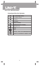
Model UT50E: OPERATING MANUAL International Electrical Symbols AC (Alternating Current). DC (Direct Current). AC or DC. Grounding. Double Insulated. Deficiency of Built-In Battery. Continuity Test. Diode. Fuse. Warning. Refer to the Operating Manual. Conforms to Standards of European Union.
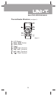
Model UT50E: OPERATING MANUAL The multimeter Structure (see figure 1) ( figure 1) 1 2 3 4 5 6 7 8 LCD Display Data Hold Button.
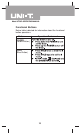
Model UT50E: OPERATING MANUAL Functional Buttons Below table indicated for information about the functional button operations Button Operation Performed POWER (Yellow Button) HOLD (Blue Button) 10
Model UT50E: OPERATING MANUAL Display Symbols (see figure 2) 10-14 ( figure 2) No. 1 2 3 4 5 6 7 8 9 10 11 Symbol Meaning Dangerous Voltages. The battery is low. Warning: To avoid false readings, which could lead to possible electric shock or personal injury, replace the battery as soon as the battery indicator appears. Indicator for AC voltage or current.The displayed value is the mean value. Indicates negative reading. Test of diode. Data hold is active. The continuity buzzer is on.
Model UT50E: OPERATING MANUAL Display Symbols (see figure 2) No. 12 13 14 Symbol nF, µF Meaning F: Farad. The unit of capacitance. µF: Microfarad.1 x 10-6 or 0.000001 farads. nF: Nanofarad. 1 x 10⁻⁹ or 0.000000001 farads. The unit of frequency in cycles/ kHz second. Kilohertz. 1 x 10⁻³ or 1,000 hertz. Ω: Ohm. The unit of resistance. Ω,kΩ,MΩ kΩ: kilohm. 1 x 10³ or 1000 ohms. MΩ: Megaohm. 1 x 10⁶ or 1,000,000 ohms.
Model UT50E: OPERATING MANUAL Measurement Operation(1) l Make sure the Sleep Mode is not on if you found there is no display on the LCD after turning on the Meter. l Make sure the Low Battery Display is not on, otherwise false readings may be provided. l Pay extra attention to the symbol which is located besides the input terminals of the Meter before carrying out measeurement. A.
Model UT50E: OPERATING MANUAL Measurement Operation(2) Note l If the value of voltage to be measured is unknown, use the maximum measurement position (1000V) and reduce the range step by step until a satisfactory reading is obtained. l The LCD displays “1” indicating the existing selected range is overloaded, it is required to select a higher range in order to obtain a correct reading. l In each range, the Meter has an input impedance of approx. 10MΩ.
Model UT50E: OPERATING MANUAL Measurement Operation(3) The AC voltage measurement has 4 measurement positions on the rotary switch: 2V, 20V, 200V and 750V To measure AC Voltage, connect the Meter as follows: 1. 2. 3. o Insert the red test lead into the VΩ C terminal and the black test lead into the COM terminal. Set the rotary switch to an appropriate measurement position in V range. Connect the test leads across with the object being measured.
Model UT50E: OPERATING MANUAL Measurement Operation(4) C. DC Current Measurement (see figure 4) black red ( figure 4) Warning Never attempt an in-circuit current measurement where the open circuit voltage between terminals and ground is greater than 60V DC or 30V rms. If the fuse burns out during measurement, the Meter may be damaged or the operator himself may be hurt. Use proper terminals, function, and range for the measurement.
Model UT50E: OPERATING MANUAL Measurement Operation(5) Note l If the value of current to be measured is unknown, use the maximum measurement position (20A) and 20A terminal, and reduce the range step by step until a satisfactory reading is obtained. l When current measurement has been completed, disconnect the connection between the testing leads and the circuit under test. D.
Model UT50E: OPERATING MANUAL Measurement Operation(6) 3. 4. 5. Set the rotary switch to an appropriate measurement position in A range. Break the current path to be tested. Connect the red test lead to the more positive side of the break and the black test lead to the more negative side of the break. Turn on power to the circuit. The measured value shows on the display.
Model UT50E: OPERATING MANUAL Measurement Operation(7) Warning To avoid damages to the Meter or to the devices under test, disconnect circuit power and discharge all the high-voltage capacitors before measuring resistance. The resistance ranges has 7 measurement positions on the rotary switch: 200Ω, 2kΩ, 20kΩ, 200kΩ, 2MΩ, 20MΩand 200MΩ . To measure resistance, connect the Meter as follows: o 1. Insert the red test lead into the VΩ Cterminal and the black test lead into the COM terminal. 2.
Model UT50E: OPERATING MANUAL Measurement Operation(8) F. Measuring Diodes & Continuity (see figure 6) Warning To avoid damage to the Meter or to the equipment under test, disconnect circuit power and discharge all high-voltage capacitors before measuring diodes and continuity. red black ( figure 6) Testing Diodes Use the diode test to check diodes, transistors, and other semiconductor devices.
Model UT50E: OPERATING MANUAL Measurement Operation(9) 3. For forward voltage drop readings on any semiconductor component, place the red test lead on the component’s anode and place the black test lead on the component’s cathode. The measured value shows on the display. Note l In a circuit, a good diode should still produce a forward voltage drop reading of 0.5V to 0.8V; however; the reverse voltage drop reading can vary depending on the resistance of other pathways between the probe tips.
Model UT50E: OPERATING MANUAL Measurement Operation(10) l When continuity testing has been completed, disconnect the connection between the testing leads and the circuit under test. G. Frequency Measurement (see figure 7) red black ( figure 7) Warning To avoid harm to you or damages to the Meter, do not attempt to measure voltages higher than 60V in DC or 30V rms in AC although readings may be obtained.
Model UT50E: OPERATING MANUAL Measurement Operation(11) Note l When Hz measurement has been completed, disconnect the connection between the testing leads and the circuit under test. H. Temperature Measurement (see figure 8) red black ( figure 8) Warning To avoid harm to you or damages to the Meter, do not attempt to measure voltages higher than 60V in DC or 30V rms in AC although readings may be obtained. o The temperature measurement range is from -40 C~ o 1000 C.
Model UT50E: OPERATING MANUAL Measurement Operation(12) Note l The Meter automatically displays the temperature value inside the Meter when there is no temperature probe connection. l The included temperature probe can only be measured up to 250. For any mesaurement higher than that, the rod type temperature probe must be used instead. l When temperature measeuremnet has been completed, disconnect the connection between the testing leads and te circuit under test. I.
Model UT50E: OPERATING MANUAL Measurement Operation(13) To measure capacitance, connect the Meter as follows: o 1. Insert the red test clip or red test lead into the VΩ C terminal and the black test clip or black test lead into the mA terminal. 2. Set the rotary switch to an appropriate measurement position in Fcx range. 3. Connect the test leads across with the object being measured. The measured value shows on the display.
Model UT50E: OPERATING MANUAL Sleep Mode To preserve battery life, the Meter automatically turns off if you do not turn the rotary switch or press any button for around 10 minutes. At that time, the Meter consumes around 10µA current. The Meter can be activated by pressing the POWER two times. Turning on the Auto Display Backlight The Meter has a built-in sensor. Therefore the Display Backlight turns on and off automatically depending on the brightness of the environment.
Model UT50E: OPERATING MANUAL General Specifications l l l l l l l l l l l l l l l l l l Maximum voltage between any Terminals and Grounding : DC 1000V or AC750V. Fused Protection for Input Terminal : 0.5A, 250V fast type, 5x20mm. Fused Protection for 20A Input Terminal : Un-fused. Range : Manual ranging. Maximum Display : Display:19999. Mesaurement Speed : Updates 2~3 times/second. o o o o Temperature:Operating : 0 C~40 C (32 F~104 F); o o o o Storage : -10 C~50 C( 14 F~122 F).
Model UT50E: OPERATING MANUAL 28
Model UT50E: OPERATING MANUAL Accuracy Specifications(2) C. DC Current Range Resolution Accuracy Overload Protection 2mA 0.0001mA (0.5%+5) 0.5A. 250V fast type fuse, 5x20mm 20mA 0.001mA (0.8%+5) 200mA 0.01mA Un-Fused (2%+10) 20A 0.001A Remarks: l At 20A Range: For continuous measurement 10 seconds and interval not less than 15 minutes. l Measurement voltage drop: Full range at 200mV. D. AC Current Range Resolution Accuracy Overload Protection 20mA 0.001mA (0.8%+10) 0.5A. 250V fast type (1.
Model UT50E: OPERATING MANUAL Accuracy Specifications(3) E. Resistance Test Range Resolution Accuracy Overload Protection (0.5%+10) 0.01Ω 200Ω 0.0001kΩ 2kΩ 0.001kΩ 20kΩ 250V DC (0.3%+1) or AC rms 0.01kΩ 200kΩ 2MΩ 0.0001MΩ (0.5%+12) 20MΩ 0.001MΩ [5%(reading-1000)+10] 200MΩ 0.01MΩ Remarks: l At 200MΩ range , test lead is in short circuit , and it is normal to display1000 digits. During measurement, subtract the1000 digits from the reading. F. Diodes and Continuity Test Range Resolution Input Protection 0.
Model UT50E: OPERATING MANUAL Accuracy Specifications(4) H. Temperature Range o Accuracy Resolution o -40 C~0 C o o 0 C~400 C o o 400 C~1000 C (3%+40) (1%+30) (2%+50) o 0.1 C Overload Protection 250V AC I. Capacitance Range Resolution Accuracy Overload Protection (3%+40) 2nF 0.0001nF 20nF 0.001nF 250V AC (4%+10) 2µF 0.0001µF 20µF 0.001µF Remarks: Testing signal: approx. 400Hz 40mV rms.
Model UT50E: OPERATING MANUAL Maintenance(1) This section provides basic maintenance information including battery and fuse replacement instruction. Warning Do not attempt to repair or service your Meter unless you are qualified to do so and have the relevant calibration, performance test, and service information. To avoid electrical shock or damage to the Meter, do not get water inside the case. A. General Service l Periodically wipe the case with damp cloth and mild detergent.
Model UT50E: OPERATING MANUAL Maintenance(2) Warning To avoid false readings, replace the battery as soon as the battery indicator appears. To replace battery: 1. 2. 3. 4. 5. 6. Disconnect the connection between the testing leads and the circuit under test, and remove the testing leads away from the input terminals of the Meter.
Model UT50E: OPERATING MANUAL Maintenance(3) 6. Rejoin the case bottom and the case top, and install the screw and rubber feet Replacement of fuses is seldom required. Burning of a fuse always results from the improper operation. ~ END ~ This operating manual is subject to change without notice.
Model UT50E: OPERATING MANUAL 35
Model UT50E: OPERATING MANUAL Copyright 2001 Uni-Trend International Limited. All rights reserved. Manufacturer: UNI-TREND TECHNOLOGY(DONG GUAN)LIMITED Address: Dong Fang Da Dao, Bei Shan Dong Fang Industrial Development District, Hu Men Town, Dong Guan City, Guang Dong Province, China Headquarters: Uni-Trend International Limited Address: Rm901, 9/F, Nanyang Plaza 57 Hung To Road Kwun Tong Kowloon, Hong Kong Tel: (852) 2950 9168 Fax: (852) 2950 9303 Email: info@uni-trend.com http://www.uni-trend.