Mercury Ultratracer UT-3000 Operating Manual English Version 2.11 Manufacturer: Mercury Instruments GmbH Liebigstrasse 5 85757 Karlsfeld/Germany service@mercury-instruments.
page 2 General information for safe operation Caution: WARNING: While operating the UT-3000 or the Automatic Calibration Unit, parts of its interior are under high voltage. UV-beams are produced inside the instrument. If safety regulations are ignored physical and/or material damages could occur. Only qualified personnel should be authorised to operate the UT-3000 and its accessories. Conditions for correct function of the UT-3000 system are careful storage and proficient operation and maintenance.
page 3 with the instrument. The instructions provided in the operation manual have strictly to be followed. The calibration device (Automatic Calibration Unit and Manual Calibration Unit) contains elemental mercury. Damage which may lead to a leakage has strictly to be avoided. Calibration device must only be opened and/or repaired by qualified and specially trained persons. Calibration device has to be protected from shocks and must never be tilt or turned over.
page 4 Contents GENERAL INFORMATION FOR SAFE OPERATION........................................................................................2 1. GENERAL DESCRIPTION ...................................................................................................................................7 1.1 APPLICATIONS.....................................................................................................................................................7 1.2 MEASURING PRINCIPLE ....................
page 5 5.2 DEVICE DATA ....................................................................................................................................................50 5.3 SHOW FLOW ......................................................................................................................................................50 5.4 PURGE REPETITIONS (FOR AUTOMATIC CALIBRATION OPTION ONLY) ........................................................50 5.
page 6 8. VERSION FOR HG DETERMINATION IN NATURAL GAS AND OTHER HYDROCARBON GASES (TEDLAR® BAG VERSION) ...................................................................................................................................80 8.1 SAMPLING SYSTEM FOR MERCURY DETERMINATION IN NATURAL GAS ..........................................................80 8.2 SETUP FOR CONTINUOUS MEASUREMENT OF HG IN NATURAL GAS.................................................................83 8.
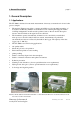
1. General Description page 7 1. General Description 1.1 Applications The UT-3000 is dedicated for automatic measurement of mercury concentrations in air and other gaseous samples. • • • • • • • • • • • • • The mercury Ultratracer provides a compact and reliable tool for automatic measuring of Total Gaseous Mercury (TGM) in air at ultratrace levels.
1. General Description FIGURE: FORMATION OF SMOG IN A CITY (KUALA LUMPUR) FIGURE: PIPELINE FOR NATURAL GAS (RUSSIA) page 8 FIGURE: THE UT-3000 IN OPERATION: MONITORING OF URBAN AIR QUALITY (MUNICH). FIGURE: ANALYSIS OF MERCURY IN NATURAL GAS USING THE UT-3000 WITH THE TEDLAR BAG TECHNIQUE FIGURE: MEASUREMENT OF MERCURY IN NATURAL GAS (EGYPT) Mercury Instruments Analytical Technologies UT-3000-E_V2.11.docx 31.07.
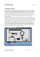
1. General Description page 9 1.2 Measuring principle The UT-3000 uses the Mercury Instruments GoldTrap to capture total gaseous mercury (TGM) directly from the sample. GoldTraps work because mercury sticks to gold at room temperature. The sample gas is pulled through a 0.45 micron PTFE filter and then passes the trap. The gas continues to flow through the trap but the mercury stays behind--trapped on the gold.
2. Installation page 10 2. Installation 2.1 Preparation for Operation The UT-3000 is unpacked and placed on a flat surface (e.g. table). The handle can be adjusted in several steps in order to be used for carrying the instrument or as a base to position it on a bench (only if applicable; there is also a version for 19” rack mount available). FIGURE: ADJUSTMENT OF CARRYING HANDLE The sample inlet filter (0.45 µm PTFE) is unpacked.
2. Installation page 11 2.2 Electrical power supply The voltage of the power source has to be the same as the operation voltage indicated on the rating plate of the UT-3000. One end of the included power cord has to be connected to the power cord receptable on the back of the UT-3000. The opposite end has to be plugged into an appropriate power outlet. For operation turn on the UT-3000 by pushing the power switch on the back plate to position I. FIGURE: REAR PANEL OF UT-3000 2.
2. Installation page 12 internal dipswitch on the backplane (see picture below) you can use this RS232-socket instead of the USB with an appropriate 1:1 cable (part-no. 202-07) for the output of measuring values. FIGURE: BACKPLANE WITH DIPSWITCH BETWEEN USB (FACTORY SETTING) AND RS232 RS 232 5 9 1 Pin Nr. 5 3 2 GND RxD TxD 6 FIGURE: SERIAL RS232 OUTPUT SOCKET ON INSTRUMENTS REAR SIDE Mercury Instruments Analytical Technologies UT-3000-E_V2.11.docx 31.07.
2. Installation page 13 Data are transferred as ASCII-characters every time a measurement cycle has been completed. They can be received and filed on the PC using a terminal program, for example Windows Hyper Terminal. The parameters for data transfer are: 9600 Baud / 8 Data bits/ 1 Stop bit/ no Parity and Xon/ Xoff. The data set has following format: Date Time Status Volume Reading [CR][LF] One data set has 34 bytes, end is carriage return and line feed.
2. Installation page 14 2.4.2 Connection of an Automatic Calibration Unit If an Automatic Calibration Unit is installed together with the UT-3000, both instruments have to be connected before starting operation. a) Use the connecting cable which has two 4-pin round plugs and plug it into the sockets on the rear side of the instruments marked “Temperature” and “PT100”. b) Take the cable with the 9-pin DSUB plugs.
3. Operating instructions page 15 3. Operating instructions 3.1 Turning on the UT-3000 Do not operate the UT-3000 without the sample inlet filter installed in place. If this precaution is ignored, the system, especially the GoldTrap, may be damaged by dust particulate. The UT-3000 version for use with an Automatic Calibration Unit must not be operated without the connecting tubing of the Automatic Calibration Unit connected to the UT3000 (see chapter 4.2.1).
3. Operating instructions page 16 FIGURE: MAIN MENU Following functions can be selected from the main menu: F1: Start Measuring = measurement cycle starts with automatic sampling, followed by gold trap heating and atomic absorption measurement. F2: Set Sample Parameters = set sample volume or measurement cycle duration. F3: Data Logger = data logger management: switch on/off data logger, display logged data, transfer logged data to PC, clear logged data.
3. Operating instructions page 17 3.3 Basic Settings For the first measurement settings in the Service Menu have to be made. Press ESC-Service in the main menu to go to the service menu. Now you have to enter a service code. Follow the instructions given in chapter 5 in order to perform the required settings. 3.4 Set Sample Parameters 3.4.1 Set Sample Volume Press F2-Set Sample Parameters in the main menu and activate “Set sample volume” by moving the arrow to the corresponding line.
3. Operating instructions page 18 3.4.2 Set Cycle Duration Press F2-Set Sample Parameters in the main menu and activate “Set Cycle Duration” by moving the arrow to the corresponding line. Then press F2 and enter the desired cycle duration. Characters can be deleted with the - key. The according sample volume is automatically calculated and displayed.
3. Operating instructions page 19 3.4.3 Auto Range Volume (only for Natural Gas / Tedlar Bag Version) If Auto Range is activated the sample volume will be automatically adjusted according to the mercury concentration of the sample. After Start Measuring the smallest possible sample volume is selected automatically. If the absorbance signal is low, the sample volume will be increased after each measurement until the absorbance is within the optimum range. 3.
3. Operating instructions page 20 FIGURE: SIGNAL PEAK DURING THERMAL DESORPTION OF THE GOLDTRAP. Zeroing Heating Sampling Trap Cooling Purge Cell Trap Cleaning Trap Cooling Trap Cooling Purge Cell Trap Cleaning Cooling UT-3000 Zeroing Heating Sampling Cleaning Cooling UT-3000 ng (Tedlar Version only) FIGURE: UT-3000: MEASUREMENT CYCLE Sampling 5 s to 15 min; depending on sample volume Zeroing Heating / Cleaning 11 s 20 s Cooling 45 s for sample vol.
3. Operating instructions page 21 3.6 Data Logger The internal data logger of the UT-3000 can store data of up to 5000 measurements. The maximum logging duration depends on the set sample volume, for a sample volume of 10 l the logging capacity will be approximately 60 days. If F3- Data Logger is selected in the main menu, the Logger Menu is displayed. F1- Logger Mode: the logger function can be switched on or off. F2- Show Logdata: the logged readings are displayed as a bar graph.
3. Operating instructions page 22 For transferring the stored data to a PC the USB output of the UT-3000 has to be connected to an USB interface of the PC. If you want to use the RS232 output, you have to change the factory setting (USB) first (see 2.4.1), then connect the RS232 output of the UT-3000 with a serial interface (COM1 or COM 2) of the PC, using a 1:1 connection cable. Two sockets are available on the instrument back panel (see also chapter 3.5.
3. Operating instructions page 23 Select Direct Connection COM1 (or COM2 if used) and press OK. Select Port Settings: 9600 bits per second / 8 data bits / parity: none / stop bit: 1 / Flow Control: hardware.Press the OK-bar. Mercury Instruments Analytical Technologies UT-3000-E_V2.11.docx 31.07.
3. Operating instructions page 24 Select the Transfer pull down menu. Select Capture Text. Enter file name and press Start. Press F3-Send logdata to PC on the UT-3000. The logged data are now transferred from the UT-3000 to the PC. Starting date, starting time, sample volume and measurement data are transferred in this order. Data sets are separated by a carriage return. 3.6.3 Delete logged data Select the Logger Mode as described above under 3.5. Press F4- clear Logdata.
3. Operating instructions page 25 FIGURE: LOGGED DATA IMPORTED INTO EXCEL: DATE, TIME, SAMPLE VOLUME, MERCURY CONCENTRATION [NG/M³] Mercury Instruments Analytical Technologies UT-3000-E_V2.11.docx 31.07.
3. Operating instructions page 26 3.6.5. Using the HG-Transfer Software for Data Transfer to a PC Calibration and analysis data are sent via serial output of the UT-3000 to a connected computer using the Hg-Transfer software (comes with the instrument). The Hg-Transfer software has to be installed on the connected computer before data are transferred. Data can be displayed, stored (as .txt file or EXCEL® file) and printed. Figure: Hg-Transfer software main screen.
3. Operating instructions page 27 Transferring of the data from the UT-3000 to the PC is started by clicking onto the start icon. During measuring there is a continuous transfer of readings. The following data are shown: Date Time Status Sample Volume Measured Value Mercury Instruments Analytical Technologies UT-3000-E_V2.11.docx 31.07.
3. Operating instructions page 28 When there are already logged data stored in the UT-3000, the whole log-file can be sent to the PC using the Hg-Transfer-Software. The values displayed in the Hg-Transfer window can be stored with the Save Logfile command (EXCEL® format). With the Save Continuously command results of a running measurement are continuously stored (EXCEL® format). With pressing About (i) you can check which version of hg-Transfer-Software you are using.
4. Calibration page 29 4. Calibration A calibration is recommended to be performed regularly according to applied quality standards. Go to the main menu and press F4: Calibration. In the Calibration Mode menu you can select: F1- to show the last performed calibration F2- to show the history of all calibration data (can be deleted with F4) F3- to perform a span check F4- to perform a new calibration. 4.1 Show actual calibration Press F1 in the Calibration Mode menu.
4. Calibration page 30 4.2 Show all calibrations Press F2 in the Calibration Mode menu. A list indicating all previously stored calibrations is displayed. The three-letter-code in the right column means: man manual calibration aut automatic calibration err calibration data of an automatic calibration were out of range; in this case the data of the previous calibration are used. Allowed range of calibration equation: Y= aX+b; where 0.00002
4. Calibration page 31 4.3 Perform Span Check If F3- Perform Span Check is selected in the Calibration Mode menu a manual span check can be performed. A calibration unit (see 4.4.2) has to be connected by cable (Pt100), this tells the analyzer the mercury concentration of the calibration gas.
4. Calibration page 32 F1 is pressed in the Calibration Mode menu in order to perform a manual calibration. Now you can select if a known mass of mercury or a known volume of mercury calibration gas is injected into the calibration gas port: F1- Enter pg or F2- Enter µl. Note: the F2- Enter µl command can only be used with the Static Calibration Set (available as an accessory to the UT-3000) connected to the UT-3000. Manual Calibration F1 Enter pg F2 Enter µl F2 Cal.
4. Calibration page 33 The calibration is carried out by following steps: a) Make sure a new septum has been inserted in the instrument calibration port. b) Press F1- Enter pg. c) Type the mass of mercury [in pico-gram Hg] which is contained in the injected volume and press ENT. d) Fill the syringe to be used with calibration gas from the calibration device. e) Push the capillary of the syringe through the septum of the calibration port on the front panel of the UT-3000 and inject the calibration gas.
4. Calibration page 34 Waiting time 10 sec. End of Calibration If the last calibration standard has been injected, press F1- End. Now the calibration function is calculated automatically. An outlier is marked as a square. It can be accepted to be included in the calibration function (F1- Yes) or it can be excluded from the calibration function (F2- No). If the outlier is not accepted (F2- No), the user is asked to repeat the calibration point. On a second page calibration data are displayed.
4. Calibration page 35 On a third page the parameters of the calibration function are displayed. The main menu is displayed again after the calibration mode is left. Practical recommendations for performing a calibration: Mercury masses should be within the same range like the measuring range. Static calibration sources (= mercury filled bottles with headspace) deliver calibration gas with comparatively high mercury concentrations (ca. 12 - 14 pg/µl at room temperature). For a low measuring range of 0.
4. Calibration page 36 4.4.2 Manual Calibration: Enter µl A Mercury Instruments Static Calibration Set is connected to the UT-3000. The user has only to enter the volume of the injected calibration gas and the instrument automatically calculates the mercury mass from volume injected and calibration cell temperature. For calibrations in the lowest measuring range it is recommended to use volumes from 1 µl to 10 µl.
4. Calibration page 37 The Mercury Instruments Calibration System consists of a specially designed mercury vessel surrounded by an aluminium jacket that is cooled by a thermoelectric cooler. The temperature of the mercury vessel is exactly measured with a high precision temperature sensor. The mercury chamber contains elemental mercury of high purity. The electronic temperature sensor has to be connected to the UT-3000 ULTRATRACER using the cable delivered with the system.
4. Calibration page 38 e) Purge the syringe with calibration gas by pulling and pushing the plunger slowly a few times. Then pull the plunger a little bit further than it is necessary to get the desired volume and pull the syringe vertically out from the septum. f) Move the plunger exactly to the desired volume and push the tip of the syringe capillary into the septum of the of the calibration port on the front panel of the UT-3000.
4. Calibration page 39 Manual Calibration F1 Enter pg F2 Enter µl F2 Cal. Mode Y=aX ESC <<< Back 3. The temperature and the saturation concentration of the calibration cell will be displayed. Type the volume of mercury which is to be injected and press ENT. For the first calibration point it is recommended to enter “0” for the volume, in this case no calibration gas has to be injected. 4.
4. Calibration page 40 FIGURE: PULLING A VOLUME OF CALIBRATION GAS FROM THE CALIBRATION CELL WITH A 10 µL SYRINGE . NOTE: hold the syringe in a vertical position to avoid contamination ! FIGURE: INJECTION OF CALIBRATION GAS INTO THE CALIBRATION PORT OF THE UT-3000 4.4.3 Examples for calibration functions Mercury Instruments Analytical Technologies UT-3000-E_V2.11.docx 31.07.
4. Calibration page 41 The calibration is linear over a wide range up to ca. 5000 pg Hg absolutely (equivalent to 5 µg/m³ for 1 litre sample volume or 0.5 µg/m³ for a 10 l sample volume). Above this range the calibration is automatically calculated using a polynomial function which is useful up to ca. 15000 pg Hg (equivalent to 15 µg/m³ for a 1 litre sample volume). Calibration UT-3000 06.12.
4. Calibration page 42 FIGURE: CALIBRATION GRAPH IN LOW RANGE (0-3,5 NG/M³) WITH CONFIDENCE RANGE Mercury Instruments Analytical Technologies UT-3000-E_V2.11.docx 31.07.
4. Calibration page 43 4.5 Perform New Calibration: Automatic Calibration (Option) The UT-3000 Ultratracer can be equipped with the Automatic Calibration Unit which is available as an accessory. This unit has a Peltier element cooled mercury saturation chamber, from which saturated air is drawn by means of a digital syringe. This air is injected automatically in a stream of zero air entering the UT-3000. It is recommended to place or mount this unit under the UT-3000.
4. Calibration page 44 FIGURE: CONNECTION OF TUBING ON BACK SIDE OF UT-3000 AND OF AUTOMATIC CALIBRATION UNIT 4.5.2 Activating the Automatic Calibration Function Switch on the Automatic Calibration Unit first, then switch on the UT-3000. After Lamp has stabilized and the main menu is displayed press ESC and enter the code 777 + ENT. Now activate the automatic calibration mode. Press ESC again to return to the main menu. Mercury Instruments Analytical Technologies UT-3000-E_V2.11.docx 31.07.
4. Calibration page 45 4.5.3 Cal. Concentration F2- Automatic Calibration is selected in the Calibration Mode menu. Now press F1-Cal. Concentration to enter concentrations used for calibration. Up to twelve calibration points can be entered. If finished press ESC. 4.5.4 Cal. Interval F2- Cal.
4. Calibration page 46 4.5.5 Manual Start of the Automatic Calibration F3- Start automatic Calibration is selected in the Calibration Mode menu. Now an automatic calibration is immediately started using the concentrations entered under F1-Cal. Concentration.
4. Calibration page 47 After that there is again a short cleaning sequence of the GoldTrap: Heating / Trap Cooling / Zeroing / Trap Cleaning / Trap Cooling / Syringe Conditioning The amount of indicated steps are calculated from the concentration levels you have fixed in the calibration concentration menue (4.5.3). After a another short zeroing you get the heating peak of the injected mercury concentration. 4.5.
4. Calibration page 48 4.5.7 Empty Syringe F4- Empty Syringe is selected in the Calibration Mode menu. By pressing F4 this function can be switched on or off. If Empty Syringe is On, then after each mercury injection the syringe is filled with air and re-injected into the gold trap. 4.5.8 Cal. Mode Page 2 of the Automatic Calibration Menu, press F1- Cal. Mode.
5. Service-Menu page 49 5. Service-Menu If ESC- Service is pressed in the main menu the service code input mask will appear on the display. Enter the code 3 2 1 + ENT Now the Service menu is displayed. In the centre of the bottom line the temperature of a connected calibration device is indicated. Mercury Instruments Analytical Technologies UT-3000-E_V2.11.docx 31.07.
5. Service-Menu page 50 5.1 Set Date and Time Press F1- Set date / time in the service menu. The date can be edited by pressing F1 and the time by pressing F2. 5.2 Device Data In this screen information for the service engineer is displayed (operational hours, lamp voltage, heating coil cycles, software version) 5.3 Show Flow In this screen the flow for sampling and the flow during thermal desorption of the mercury from the GoldTrap (heating flow) can be read. a) Heating flow: press F1.
5. Service-Menu page 51 5.5 Change Syringe (for Automatic Calibration Option only) This function is only available when the Automatic Calibration function has been activated (Service code 777). It is necessary for change of the syringe inside the Automatic Calibration Unit. The command Change Syringe moves the piston of the syringe to a 50 % position which is necessary to remove the syringe. The Reset command pushes the piston back again into the syringe. 5.
5. Service-Menu page 52 5.6.2 Set Measuring Calibration By pressing F2 – Set Meas-Calibration you can enter manually the values of the measuring calibration, in case they are deleted. 5.6.3 Set T-Cal. Cell Calibration By pressing F3 – Set T-Cal.Cell Calibration you can enter manually the values for the calibration of the temperature sensor of the calibration device (either manual or automatic calibrator). Service Mode Y = .......X +/- 0....... F1 Set gradient F2 Set constant ESC <<< Back 5.
5. Service-Menu page 53 not close to 0.00000 and still decreasing. This may be due to extremely high mercury concentration or high benzene concentrations in the sample. 5.10 Set Status In this window the function of the status contacts can be programmed, so that they will be opened or closed when activated. Service Mode Mode Set Status F1 Status active opened / closed ESC <<< Back Mercury Instruments Analytical Technologies UT-3000-E_V2.11.docx 31.07.
5. Service-Menu page 54 5.11 Special Service Codes Following codes are available: Code: Function: Standard Service Menu, see beginning of this chapter 321 Standard / Tedlar Bag Mode 191 222 333 753 777 881 987 999 Offset T Cal.Cell / Zero Offset / Heating Flow / Heating Flow Regulate Evaluation Graph on/off Flow Calibration (10 l/min – 3 points; 40 l/min – 3 points) Calib.
6. Maintenance page 55 6. Maintenance 6.
6. Maintenance 830-17 830-20 830-24 830-95 830-96 830-98 840-02 840-03 840-04 page 56 Calibration port, complete, stainless steel Holder for GoldTrap, incl. electronics Particle filter, 60 µ; stainless steel Tubing, complete set Fuse set Service kit Pressure relief valve T-joint Backplane USB with 40p flatband-connection to interface board Mercury Instruments Analytical Technologies UT-3000-E_V2.11.docx 31.07.
6. Maintenance page 57 6.2 Technical drawings Mercury Instruments Analytical Technologies UT-3000-E_V2.11.docx 31.07.
6. Maintenance page 58 FIGURE: UT-3000 ID-NUMBERS OF PARTS Mercury Instruments Analytical Technologies UT-3000-E_V2.11.docx 31.07.
6. Maintenance page 59 UT-3000: ID-NUMBERS OF TUBING REMARKS: 1. FOR TEDLAR BAG VERSION TUBING NO. 14 IS REPLACED BY TUBING NO.14T AND TUBING NO. 15 IS OMITTED. 2. FOR VERSION WITH AUTOMATIC CALIBRATION UNIT TUBING NO. 2 AND 3 INCLUDING COMPONENTS NO. 101-21/201-04 (WHICH ARE PLACED IN THE AUTOMATIC CALIBRATION UNIT) ARE REPLACED BY TUBING NO.3S Mercury Instruments Analytical Technologies UT-3000-E_V2.11.docx 31.07.
6. Maintenance Mercury Instruments Analytical Technologies page 60 UT-3000-E_V2.11.docx 31.07.
6. Maintenance Mercury Instruments Analytical Technologies page 61 UT-3000-E_V2.11.docx 31.07.
6. Maintenance page 62 FIGURE: AUTOMATIC CALIBRATION UNIT, PART NUMBERS SEE SPARE PARTS LIST CHAPTER 8.4 Mercury Instruments Analytical Technologies UT-3000-E_V2.11.docx 31.07.
6. Maintenance page 63 FIGURE: AUTOMATIC CALIBRATION UNIT, ID-NUMBERS OF TUBING Mercury Instruments Analytical Technologies UT-3000-E_V2.11.docx 31.07.
6. Maintenance page 64 6.3 Error messages 6.3.1 Lamp ! The installed electrodeless mercury lamp is monitored permanently. If its performance drops under a certain limit the warning „LAMP!” indicates that it should be replaced within the next days. 6.3.2 Sampling Flow out of Range! This warning appears if the flow during sampling is out of the allowed range (38 – 42 l/h).
6. Maintenance page 65 6.3.7 Temp out of Range ! See instruction manual! This warning indicates, that during calibration with a connected manual or automatic calibration device the temperature is <6°C or >35°C. 6.3.8 Pump ! (flashing) This warning indicates, that the flow counter is out of range (1-100 is correct) and pump voltage is at its upper limit (12V)! Reason may be a malfunction of the pump, plugged valves 830-08 or 830-03, not correctly adjusted valves 830-08 or 830-03. 6.3.
6. Maintenance page 66 6.3.15 Warning No. 70; Check Calibration Data! This warning indicates that the data of the last automatic calibration have been erased. A new calibration has to be performed or manually entered in the service menu. 6.3.16 Warning No. 80; RS232 Communication Error; Connect Syringe! This warning indicates, that a communication error between UT-3000 and the automatic calibration module has occurred. 6.3.17 Warning No.
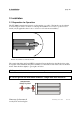
6. Maintenance page 67 6.4 Troubleshooting 6.4.1 Unusual Measuring Peaks An example for a non-typical peak is shown in the picture below. The peak is more of triangular shape and the signal drops to negative values after the peak. Figure: Example for an non-typical desorption peak The reason may be precipitation in the tubing at the outlet of the GoldTrap (= tubing which connects GoldTrap and optical cell, see picture below). In this case it is recommended to replace the contaminated tubing.
6. Maintenance page 68 6.5 Routine Maintenance 6.5.1 Replacement of Membrane Filter Under normal circumstances the sample membrane filter has to be inspected regularly. If a deposit of particulate matter or staining is visible, the filter has to be replaced. For filter replacement, turn the filter slightly and pull it out. Insert the new filter into the filter holder and push it carefully over the white nozzle in the centre of the filter holder. Turn the filter slightly. 6.5.
6. Maintenance page 69 B) Automatic Calibration Unit (option) Inside the Automatic Calibration Unit there are four filter cartridges: two activated carbon cartridges, one particulate filter cartridge, and one desiccant cartridge. These should be replaced annually. First loosen the two screws in the back of the Automatic Calibration Unit and remove top cover of the case. Do not pull with force as an ground wire is mounted to the cover. The ground wire can be disconnected by pulling the plug on one end.
6. Maintenance page 70 6.6 Fuses The main fuse compartment is located on the rear of the instrument between the power cord receptacle and the power switch. It contains two fuses. Pull power plug before opening the fuse compartment! Fuse type: the rating of the fuses to be used as spares depends on the operation voltage indicated on the rating plate of the instrument: 230V Operation voltage: Fuse type T 1.6 A (time lag) 115V Operation voltage: A third fuse (3.
6. Maintenance page 71 The Automatic Calibration Unit has two main fuses which are located in the fuse compartment. This is located on the rear of the instrument between the power cord receptable and the power switch. Pull power plug before opening the fuse compartment! Fuse type: The rating of the fuses to be used as spares depends on the operation voltage indicated on the rating plate of the instrument: 230V Operation voltage: Fuse type T 1.0 A (time lag) 115V Operation voltage: 6.
6. Maintenance page 72 After this the GoldTrap-syringe assembly is carefully removed from the beaker with nitric acid and the open end of the plastic tube is immersed in a beaker with filled with water. The water is pulled into the syringe thus rinsing the GoldTrap and removing the nitric acid. After that the GoldTrap-syringe assembly is removed from the water filled beaker and placed over a sink or a suitable container which shall hold the purge water (= acidic water).
6. Maintenance page 73 6.8 Replacement of the GoldTrap The GoldTrap requires replacement if the slope of the calibration curve is below 0.00004. A new GoldTrap (part No. 830-11) will be inserted instead of the used one which may be returned to the manufacturer for regeneration. Pull power plug before opening the photometer! First loosen the two screws in the back of the UT-3000 photometer unit and remove top cover of the case. Do not pull with force as an ground wire is mounted to the cover.
6. Maintenance page 74 Figure: opening of the top cover of the instrument and position of GoldTrap FIGURE: DEINSTALLATION OF GOLDTRAP: (LEFT UP) REMOVING THE PLUG (RIGHT UP) REMOVING THE TUBING (LEFT) REMOVING THE GOLDTRAP Mercury Instruments Analytical Technologies UT-3000-E_V2.11.docx 31.07.
6. Maintenance page 75 6.9 Flow Adjustment (for qualified personnel only) After replacement of components which may influence the flow (GoldTrap, filters, pump) it may be necessary to readjust the flow. Select from the Service Menu Show Flow (see chapter 5.3). 6.9.1 Heating Flow Adjustment Read Heating Flow Select F1- Heating Flow. Allow to stabilize for approximately one minute. The actual flow will be indicated on the screen and should be between 9.8 l/h and 10.2 l/h.
6. Maintenance page 76 FIGURE: NEEDLE VALVES FOR HEATING FLOW ADJUSTMENT AND SAMPLING FLOW ADJUSTMENT 6.10 Gold Trap Assembly The GoldTrap is snapped into holding clamps which are mounted on an angled metal plate. This plate holds following electronic parts on its down side: (a) A driver transistor that switches the power for the heating coil of the GoldTrap, (b) An optical coupler, (c) Two resistors. Mercury Instruments Analytical Technologies UT-3000-E_V2.11.docx 31.07.
6. Maintenance Mercury Instruments Analytical Technologies page 77 UT-3000-E_V2.11.docx 31.07.
7. Technical Information page 78 7. Technical Information 7.1 Technical specifications Instrument type Manufacturer Measuring component Measurement principle Measurement wavelength UV-source Method of stabilising Optical cell Cell temperature Measuring range a) lowest range b) medium range c) screening mode Detection limit according DIN 32645 Linearity over the 0.
7. Technical Information page 79 7.3 Storage and transport The interior of the UT-3000 and the calibration device should be kept save from moisture and hard shocks. Vibrations caused by transport in a car do not harm the UT-3000. The Automatic Calibration Unit and the Manual Calibration Unit must always be carried or transported horizontal, it must never be tilt or turned over. Hard shocks must be avoided.
8. Version for Hg determination in natural gas and other hydrocarbon gases (Tedlar® Bag Version) page 80 8. Version for Hg determination in natural gas and other hydrocarbon gases (Tedlar® Bag Version) A special version of the UT-3000 analyser can be used for measurement of mercury in natural gas and derivatives. For these applications special precautions have to be made to prevent explosion. The appropriate safety regulations have strictly to be observed.
8. Version for Hg determination in natural gas and other hydrocarbon gases (Tedlar® Bag Version) page 81 Figure: Natural Gas Sampling System schematic gas flow Mercury Instruments Analytical Technologies UT-3000-E_V2.11.docx 31.07.
8. Version for Hg determination in natural gas and other hydrocarbon gases (Tedlar® Bag Version) page 82 FIGURE: NATURAL GAS SAMPLIN SYSTEM FRONT VIEW FIGURE: NATURAL GAS SAMPLING SYSTEM TOP VIEW, OPENED FIGURE: SETUP OF SAMPLING SYSTEM AND UT-3000 ANALYZER FOR HG MEASUREMENT FROM A SAMPLE CYLINDER Mercury Instruments Analytical Technologies UT-3000-E_V2.11.docx 31.07.
8. Version for Hg determination in natural gas and other hydrocarbon gases (Tedlar® Bag Version) page 83 FIGURE: SAMPLING CONTINUOUS SAMPLING OF NATURAL GAS (BENCHAMAS OFFSHORE PLATFORM; THAILAND) 8.2 Setup for continuous measurement of Hg in natural gas For automatic 24 hours per day monitoring an optional setup for continuous measurement is available. The analyser system is installed in a safe place out of the hazardous zone.
8. Version for Hg determination in natural gas and other hydrocarbon gases (Tedlar® Bag Version) page 84 8.3 UT-3000 version for analysis using a sample bag (Tedlar® Bag) NOTE: the Tedlar Bag Method described in this chapter requires the corresponding software which is installed as an option. The Tedlar Bag Method has to be activated in the Service Menu by entering the Code 191 (see also Chapter 5.10).
8. Version for Hg determination in natural gas and other hydrocarbon gases (Tedlar® Bag Version) page 85 8.3.1 Setup of the UT-3000 analyzer Safety instructions – read carefully: Place the UT-3000 onto a flat and dry surface (table). Take care that the ventilation holes on the bottom side of the analyzer are not covered by objects (like a sheet of paper, etc.) and air can free ventilate.
8. Version for Hg determination in natural gas and other hydrocarbon gases (Tedlar® Bag Version) page 86 8.3.2 Sampling of natural gas with the sample bag (Tedlar® bag) The sample bag has to be completely empty before filling with sample gas. This may be done by opening the valve of the bag, placing the bag onto a smooth and clean surface and running the back of the hand over the bag until it is totally flat. Filling must be done by connecting the sample bag with a source of positive pressure.
8. Version for Hg determination in natural gas and other hydrocarbon gases (Tedlar® Bag Version) page 87 Press F1-Start sampling to commence sample introduction into the analyzer. The instrument will draw the preset volume of sample from the bag. After the sampling has been completed the sample bag valve must be closed. The end of sampling is indicated by a beeping sound and the message: Close sample bag valve (clockwise); Remove Sample Bag.
8. Version for Hg determination in natural gas and other hydrocarbon gases (Tedlar® Bag Version) page 88 FIGURE: TEDLAR BAG VALVE WITH CONNECTING NOZZLE. OPEN AND CLOSE: HOLD THE LOWER PART WITH NOZZLE WITH ONE HAND AND TURN THE UPPER PART WITH THE OTHER HAND. FIGURE: ATTACHING THE CONNECTION TUBING TO THE TEDLAR BAG NOZZLE FIGURE: POSITION OF THE TEDLAR BAG DURING SAMPLING Mercury Instruments Analytical Technologies UT-3000-E_V2.11.docx 31.07.
8. Version for Hg determination in natural gas and other hydrocarbon gases (Tedlar® Bag Version) page 89 FIGURE: FLOW OF SAMPLE FROM TEDLAR BAG THROUGH ANALYZER DURING SAMPLING STEP FIGURE: FLOW OF CARRIER AIR AND DESORPTION OF MERCURY FROM GOLDTRAP HEATING/MEASURING STEP Mercury Instruments Analytical Technologies UT-3000-E_V2.11.docx 31.07.
8. Version for Hg determination in natural gas and other hydrocarbon gases (Tedlar® Bag Version) page 90 8.4 Select Pump Type The system can be equipped with two different pump types: a rotary vane pump or a membrane pump. According to the installed pump “rotary vane” or “membrane” has to be selected by pressing the F3-key in the service menu (3 2 1-code) on page 3.
9. Communication with external data acquisition system (option) page 91 9. Communication with external data acquisition system (option) The UT-3000 is prepared for connecting to an external data acquisition system. In this case the data acquisition system will be the master and the UT-3000 the slave. The master can send queries and commands. Results of measurements, calibration, and the set parameters can be read out, a zero check and a span check will be carried out on demand. 9.
9. Communication with external data acquisition system (option) ;E;13827; page 92 13827 = CRC16 E= error command valid for every checksum-error If the external master recognises a checksum-error, the master has to repeat the inquiry, not to send the error command to the UT-3000.
9.
9. Communication with external data acquisition system (option) ;P;19.2;43850; temp. of calibration cell = 19.2 °C ;P;K;51699; ;P;E;43511; E = single (manual) calibration ;P;I;43506; ;P;U;27130; ;P;P;14841; ;P;4;63955; ;P;1130;44505; page 94 U = µl (when manual calibration has been chosen) P = pg (when manual calibration has been chosen) calibration. interval = 4 hours (when Auto.
9. Communication with external data acquisition system (option) Inquiry: ;C;Z;V;; C = control Z = zero-check V = value (= read zero-check value) Answer: ;C;V;conc;; V = value conc = meas. Concentration in ng/m³ Example: ;C;Z;V;19197; ;C;V;1.1;22683; 19197 = CRC16 22683 = CRC16 1.
page 96 INDEX accessories 55 Applications 7 Auto Range 19 automatic calibration 43 Automatic Calibration Unit connection 14 bag sampling 84 calibration automatic 43 manually 32 Calibration Data Set 51 connection Automatic Calibration Unit 14 data output 11 electrical 11 RS232 11 Data Logger send data to PC (Hg-Transfer) 26 Declaration of Conformity 97 desiccant cartridge replacement 69 Device Data 50 dryer tube replacement 69 EC-Declaration 97 error messages 64 filter replacement of 68 filter cartridges re
page 97 APPENDIX EC-Declaration of Conformity The Company: Declares that the product: Intended purpose: Mercury Instruments GmbH Liebigstrasse 5 D-85757 Karlsfeld Germany UT-3000 Mercury Ultratracer Automatic measurement of mercury at trace concentration levels in air and other gases conforms with the basic requirements of the relevant EC directives. A conformity assessment method as provided in the directives has been executed.
page 98 (CEO) Mercury Instruments Analytical Technologies UT-3000-E_V2.11.docx 31.07.