Model UT201/202: OPERATING MANUAL Table of Contents Title Page Overview Unpacking Inspection Safety Information Rules For Safe Operation International Electrical Symbols The Meter Structure Rotary Switch Functional Buttons The Effectiveness of Functional Buttons Display Symbols Measurement Operation A. DC Voltage Measurement B. AC Voltage Measurement C. Measuring Resistance D. Testing Diodes E. Testing for Continuity F. Temperature Measurement G. AC Current Measurement Sleep Mode Specifications A.
Model UT201/202: OPERATING MANUAL 2
Model UT201/202: OPERATING MANUAL Overview This Operating Manual covers information on safety and cautions. Please read the relevant information carefully and observe all the Warnings and Notes strictly. Warning To avoid electric shock or personal injury, read the “Safety Information” and “Rules for Safe Operation” carefully before using the Meter.
Model UT201/202: OPERATING MANUAL Unpacking Inspection Open the package case and take out the Meter. Check the following items carefully to see any missing or damaged part: Item 1 2 3 4 Description English Operating Manual Test Lead Point Contact Temperature Probe (UT202 only) 1.5V Battery (AAA) Qty 1 piece 1 pair 1 piece 2 pieces In the event you find any missing or damage, please contact your dealer immediately.
Model UT201/202: OPERATING MANUAL Safety Information This Meter complies with the standards IEC61010: in pollution degree 2, overvoltage category (CAT. II 600V, CAT. III 300V) and double insulation. CAT. II: Local level, appliance, PORTABLE EQUIPMENT etc., with smaller transient overvoltages than CAT. III. CAT. III: Distribution level, fixed installation, with smaller transient overvoltages than CAT.
Model UT201/202: OPERATING MANUAL Rules For Safe Operation (1) Warning To avoid possible electric shock or personal injury, and to avoid possible damage to the Meter or to the equipment under test, adhere to the following rules: l Before using the Meter inspect the case. Do not use the Meter if it is damaged or the case (or part of the case) is removed. Look for cracks or missing plastic. Pay attention to the insulation around the connectors.
Model UT201/202: OPERATING MANUAL Rules For Safe Operation (2) l l l l l l l l l l l l When the Meter working at an effective voltage over 60V in DC or 30V rms in AC, special care should be taken for there is danger of electric shock. Use the proper terminals, function, and range for your measurements. Do not use or store the Meter in an environment of high temperature, humidity, explosive, inflammable and strong magnetic field. The performance of the Meter may deteriorate after dampened.
Model UT201/202: OPERATING MANUAL International Electrical Symbols AC (Alternating Current). DC (Direct Current). AC or DC. Grounding. Double Insulated. Deficiency of Built-In Battery Continuity Test. Diode. Capacitance Test Fuse. Warning. Refer to the Operating Manual. Conforms to Standards of European Union.
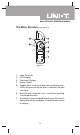
Model UT201/202: OPERATING MANUAL The Meter Structure (see figure 1) ( figure 1) 1. 2. 3. 4. 5. 6. 7. Input Terminals LCD Display Functional Buttons Rotary Switch Trigger: press the lever to open the transformer jaws. When the pressure on the lever is released, the jaws will close. Hand Guards: to protect user’s hand from touching the dangerous area. Transformer Jaws: designed to pick up the AC current flowing through the conductor. It could transfer current to voltage.
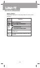
Model UT201/202: OPERATING MANUAL Rotary Switch Below table indicated for information about the rotary switch positions. Rotary Function Switch Position OFF Power is turned off. AC/DC voltage measurement. : Diode test. : Continuity test. Ω o Ω : Resistance measurement. o CF A Temperature measurement (UT202 only) AC current measurement range from 0.001A to 400.
Model UT201/202: OPERATING MANUAL Functional Buttons(1) Below table indicated for information about the functional button operations. AC voltage measurement. l Press HOLD to enter and exit the HOLD Hold mode in any mode, the Meter beeps. l Press and hold HOLD button while turning on the Meter to display full icons. MAX Press MAX to start recording and updating of maximum values. SELECT Press SELECT button to switch between o o Ω and C F .
Model UT201/202: OPERATING MANUAL The Effectiveness of Functional Buttons Not every functional buttons can be used on every rotary switch positions.
Model UT201/202: OPERATING MANUAL Display Symbols(1) (see figure 2) No. Symbol 1 AC 2 DC 3 4 5 6 7 8 9 10 Meaning Indicator for AC voltage or current Indicator for DC voltage The battery is low. Warning: To avoid false readings, which could lead to possible electric shock or personal injury, replace the battery as soon as the battery indicator appears. The Meter is in the auto range mode in which the Meter automatically selects the range with the best resolution. Test of diode.
Model UT201/202: OPERATING MANUAL Display Symbols(2) (see figure 2) No. Symbol 11 A mV, V 12 13 14 OL Meaning Amperes (amps). The unit of current. Volts. The unit of voltage.mV: Millivolt. 1x10⁻³ or 0.
Model UT201/202: OPERATING MANUAL Measurement Operation(1) A. DC Voltage Measurement (see figure 3) red black ( figure 3) Warning To avoid harms to you or damages to the Meter from eletric shock, do not attempt to measure voltages higher than 600V AC/DC, although readings may be obtained. The DC Voltage ranges are: 200.0mV, 2.000V, 20.00V, 200.0V and 600V. To measure DC voltage, connect the Meter as follows: 1. Insert the red test lead into the VΩ terminal and the black test lead into the COM terminal.
Model UT201/202: OPERATING MANUAL Measurement Operation(2) l When DC voltage measurement has been completed, disconnect the connection between the testing leads and the circuit under test and remove testing leads from the input terminals. B. AC Voltage Measurement (see figure 4) red black ( figure 4) Warning To avoid harms to you or damages to the Meter from eletric shock, do not attempt to measure voltages higher than 600V AC/DC, although readings may be obtained. The AC Voltage ranges are: 2.
Model UT201/202: OPERATING MANUAL Measurement Operation(3) Note l In each range, the Meter has an input impedance of 10MΩ. This loading effect can cause measurement errors in high impedance circuits. If the circuit impedance is less than or equal to 10kΩ, the error is negligible (0.1 or less). l When AC voltage measurement has been completed, disconnect the connection between the testing leads and the circuit under test and remove testing leads from the input terminals. C.
Model UT201/202: OPERATING MANUAL Measurement Operation(4) The resistance ranges are: 200.0 , 2.000k , 20.00k ,200k ,2.000M and 20.00M . To measure resistance, connect the Meter as follows: 1. Insert the red test lead into the V terminal and the black test lead into the COM terminal. 2. Set the rotary switch to ; resistance measurement ( ) is default or press SELECT button to select measurement mode. 3. Connect the test leads across with the object being measured. The measured value shows on the display.
Model UT201/202: OPERATING MANUAL Measurement Operation(5) D.Testing Diodes (see figure 6) red black ( figure 6) Warning To avoid damages to the Meter or to the devices under test, disconnect circuit power and discharge all the high-voltage capacitors before testing diodes. Use the diode test to check diodes, transistors, and other semiconductor devices. The diode test sends a current through the semicondutor junction, then measure the voltage drop across the junction.
Model UT201/202: OPERATING MANUAL Measurement Operation(6) Note l In a circuit, a good diode should still produce a forward voltage drop reading of 0.5V to 0.8; however, the reverse voltage drop reading can vary depending on the resistance of other pathways between the probe tips. l Connect the test leads to the proper terminals as said above to avoid error display. l The LCD will display OL indicating either open circuit or wrong polarity connection.
Model UT201/202: OPERATING MANUAL Measurement Operation(7) Warning To avoid damages to the Meter or to the devices under test, disconnect circuit power and discharge all the high-voltage capacitors before measuring continuity. To test for continuity, connect the Meter as follows: 1. Insert the red test lead into the VΩ terminal and the black test lead into the COM terminal. 2. Set the rotary switch to Ω and press SELECT button to select measurement mode. 3.
Model UT201/202: OPERATING MANUAL Measurement Operation(8) F. Temperature Measurement (UT202 Only) (see figure 8) red black ( figure 8) o o The temperature measurement ranges are -40 C~1000 C o o and -40 F~1832 F. To measure temperature, connect the Meter as follows: 1. Insert the red temperature probe into the VΩ terminal and the black temperature probe into the COM terminal. o o 2. Set the rotary switch to F C and press SELECT button o o o to select F or C measurement mode.
Model UT201/202: OPERATING MANUAL Measurement Operation(9) G. AC Current Measurement (see figure 9) ( figure 9) Warning To avoid electric shock, never measure current while the test leads are inserted into the input terminals and disconnect test leads and tested circuit connection. Never attempt an in-circuit current measuremnet where the open-circuit voltage between the circuit and the ground is greater than 600V Use proper function and range for the measurement.
Model UT201/202: OPERATING MANUAL Measurement Operation(10) Note: l To obtain accurate reading, measure only one conductor at each time. l When current measurement has been completed, disconnect the connection between the conductor under test and the jaw, and remove the conductor away from the transformer jaw of the Meter.
Model UT201/202: OPERATING MANUAL Sleep Mode To preserve battery life, the Meter automatically turns off if you do not turn the rotary switch or press any button for around 15 minutes. The Meter can be activated by turning the rotary switch or pressing any button with the following conditions: 1) When the Meter is entered Sleep Mode at temperature functions of Model: UT202, the Meter cannot be activated by turning the rotary switch to AC current ranges.
Model UT201/202: OPERATING MANUAL Specifications A.General Specifications: l Maximum voltage including transient overvoltage between any terminals and grounding: 500V rms. l l l l l l l l l l l l l Display: 3 1/2 digits LCD display, Maximum display 1999 Auto Polarity Display Overloading : Display OL or –OL Battery Deficiency : Display Measurement Speed : Updates 3 times/second.
Model UT201/202: OPERATING MANUAL Accurate Specifications(1) Accuracy: (a% reading + b digits), guarantee for 1 year. o o Operating temperature: 23 C 5 C Relative humidity: 75%R.H o Temperature coefficient: 0.1x(specified accuracy)/1 C A. AC Voltage: Auto ranging Range Resolution 2.000V 20.00V 200.0V 600V 1mV 10mV 100mV 1V Accuracy Overload Protection (1.2%+5) 600V rms (1.5%+5) Remarks: l Input impedance: 10MΩ //<100pF” l Displays effective value of sine wave (mean value response).
Model UT201/202: OPERATING MANUAL Accurate Specifications(2) C. Resistance: Auto ranging Range Resolution 200.0Ω 2.000kΩ 20.00kΩ 200.0kΩ 2.000MΩ 20.00MΩ 100mΩ 1Ω 10Ω 100Ω 1kΩ 10kΩ Accuracy Overload Protection (1.2%+2) (1%+2) 600Vp (1.2%+2) (1.5%+2) Remarks: Input impedance: 10MΩ . D. Continuity Test Range Resolution 100mΩ Accuracy Around buzzer beeps Overload Protection 600Vp50Ω the Remark: l Open circuit voltage approximate 0.45V.
Model UT201/202: OPERATING MANUAL Accurate Specifications(3) F. Temperature (UT202 Only): Range Resolution Accuracy Overload Protection o o -40~1000 C o o -40 F~1832 F -40~0 C: (3%+4) o 0~400 C: (1%+3) o 400~1000 C: (2%+10) o -40~32 F: (3%+8) o o 32 F~752 F: (1%+6) o o 752 F~1832 F: (2%+18) o 1C o 1F 600Vp G. AC Current: Auto ranging Range Resolution Accuracy Frequency Overload Response Protection <1A(4%+40) 1A(3%+30) 2.000A 0.001A 20.00A 0.
Model UT201/202: OPERATING MANUAL MAINTENANCE(1) This section provides basic maintenance information including battery replacement instruction. Warning Do not attempt to repair or service your Meter unless you are qualified to do so and have the relevant calibration, performance test, and service information. To avoid electrical shock or damage to the Meter, do not get water inside the case. A. General Service l l l l l Periodically wipe the case with a damp cloth and mild detergent.
Model UT201/202: OPERATING MANUAL MAINTENANCE(2) Warning To avoid false readings, which could lead to possible electric shock or personal injury, replace the battery as soon as the battery indicator “ ” appears. Make sure the transformer jaw and the tets leads are disconected from the circuit being tested before opening the case bottom. To replace the battery:. 1. Turn the Meter off and remove all the connections from the input terminals 2. Turn the Meter’s case top down. 3.
Model UT201/202: OPERATING MANUAL Copyright 2001 Uni-Trend Group Limited. All rights reserved. Manufacturer: Uni-Trend Technology (Dongguan) Limited Dong Fang Da Dao Bei Shan Dong Fang Industrial Development District Hu Men Town, Dongguan City Guang Dong Province China Postal Code: 523 925 Headquarters: Uni-Trend Group Limited Rm901, 9/F, Nanyang Plaza 57 Hung To Road Kwun Tong Kowloon, Hong Kong Tel: (852) 2950 9168 Fax: (852) 2950 9303 Email: info@uni-trend.com http://www.uni-trend.