Camera Network Dome Camera Quick Operation Guide 1
Network Dome Camera·Quick Operation Guide Thank you for purchasing our product. If there are any questions, or requests, please do not hesitate to contact the dealer. About This Document This manual applies to the following models. Model HNC301‐VD HNC303‐VD This manual may contain several technical incorrect places or printing errors, and the content is subject to change without notice. The updates will be added to the new version of this manual.
Network Dome Camera·Quick Operation Guide Regulatory Information FCC Information FCC compliance: This equipment has been tested and found to comply with the limits for a digital device, pursuant to part 15 of the FCC Rules. These limits are designed to provide reasonable protection against harmful interference when the equipment is operated in a commercial environment.
Network Dome Camera·Quick Operation Guide 2012/19/EU (WEEE directive): Products marked with this symbol cannot be disposed of as unsorted municipal waste in the European Union. For proper recycling, return this product to your local supplier upon the purchase of equivalent new equipment, or dispose of it at designated collection points. For more information see: www.recyclethis.info.
Network Dome Camera∙Quick Operation Guide Safety Instruction These instructions are intended to ensure that user can use the product correctly to avoid danger or property loss. The precaution measure is divided into “Warnings” and “Cautions” Warnings: Serious injury or death may occur if any of the warnings are neglected. Cautions: Injury or equipment damage may occur if any of the cautions are neglected. Warnings Follow these safeguards to prevent serious injury or death.
Network Dome Camera∙Quick Operation Guide Do not connect several devices to one power adapter as adapter overload may cause over‐heating or a fire hazard. Please make sure that the plug is firmly connected to the power socket. When the product is mounted on wall or ceiling, the device shall be firmly fixed. If smoke, odor or noise rise from the device, turn off the power at once and unplug the power cable, and then please contact the service center.
Network Dome Camera∙Quick Operation Guide Do not place the camera in extremely hot, cold (the operating temperature shall be‐30Ԩ~+60Ԩ,or ‐40°C ~ 60°C if the camera model has an “H” in its suffix), dusty or damp locations, and do not expose it to high electromagnetic radiation. To avoid heat accumulation, good ventilation is required for operating environment. Keep the camera away from liquid while in use. While in delivery, the camera shall be packed in its original packing, or packing of the same texture.
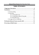
Network Dome Camera∙Quick Operation Guide Table of Contents 1 Appearance Description ............................................................... 8 2 Installation ................................................................................. 11 2.1 Disassembling ............................................................... 12 2.2 Mounting ...................................................................... 13 2.2.1 Ceiling Mounting ................................................ 13 2.2.
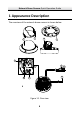
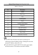
Network Dome Camera∙Quick Operation Guide 1 Appearance Description The overview of the network dome camera is shown below.
Network Dome Camera∙Quick Operation Guide Table 1‐1 Overview No. Description 1 Bubble 2 Black Liner 3 Lens 4 Mounting Base 5 Reset 6 Auxiliary Video Output 7 Serial Port 8 Micro SD Card Slot 9 Network Cable 10 Power Cable 11 Audio/Alarm Interface z Press RESET about 10s when the camera is powering on or rebooting to restore the default settings, including the user name, password, IP address, and port No., etc.
Network Dome Camera∙Quick Operation Guide Alarm/Audio Cable Interface Figure 1‐2 Audio and Alarm Interfaces 10
Network Dome Camera∙Quick Operation Guide 2 Installation Before you start: z Make sure the device in the package is in good condition and all the assembly parts are included. z Make sure all the related equipment is power‐off during the installation. z Check the specification of the products for the installation environment. z Make sure the power supply is matched with your required voltage to avoid damage.
Network Dome Camera∙Quick Operation Guide Make sure that there is no reflective surface too close to the camera lens. The IR light from the camera may reflect back into the lens causing reflection. The foam ring around the lens must be seated flush against the inner surface of the bubble to isolate the lens from the IR LEDS. Fasten the dome cover to camera body so that the foam ring and the dome cover are attached seamlessly. 2.1 Disassembling Steps: 1.
Network Dome Camera∙Quick Operation Guide 2.2 Mounting Ceiling Mounting Steps: 1. Disassemble the camera. Refer to the section 2.1. 2. Attach the drill template (supplied) to the place where you want to fix the camera. 3. According to the drill template as shown in Figure 2‐2, drill three screw holes in the ceiling. Side Cable Outlet Cable Outlet Drilling Template for Outdoor Day/Night Vandal‐proof Dome Camera Screw Hole Figure 2‐2 The Drill Template 4.
Network Dome Camera∙Quick Operation Guide want to route the cables on the surface of the ceiling. Refer to Conduit Installation on the Side for side cable routing. 5. Attach the camera to the ceiling by aligning the holes of the back box with the holes on the ceiling. 6. Secure the camera with the supplied screws as shown in Figure 2‐3. Back Box Screw Figure 2‐3 Secure the Camera 7. Route the cables through the cable hole. 8. Connect the video output connector to the monitor.
Network Dome Camera∙Quick Operation Guide Figure 2‐4 Secure Black Liner and Bubble Conduit Installation on the Side If you want to route the cables from side of the camera, you need to follow the steps below to install a conduit for cable routing. Steps: 1. Rotate the water‐proof plug counterclockwise to remove it from the camera.
Network Dome Camera∙Quick Operation Guide Water‐proof Plug Side Cable Outlet Figure 2‐5 Remove the water‐proof plug 2. Route the power cable and network cable through the side outlet to the conduit. 3. Align and rotate clockwise the conduit to the side outlet tightly.
Network Dome Camera∙Quick Operation Guide For wall mounting, position the side outlet directly downward for water‐proof. Downward Figure 2‐7 Side Outlet Direction 2.2.2 Ceiling Mounting with Gang Box Steps: 1. Disassemble the camera. Refer to the section 2.1. 2. Install the gang box in the ceiling. 3. Attach the mounting base to the gang box with two screws.
Network Dome Camera∙Quick Operation Guide Mounting Base Figure 2‐8 In‐ceiling Mount 4. Route the cables through the hole in the center of the mounting base. 5. Align the camera with the mounting base. 6. Tighten the screws to secure the camera with the mounting base. 7. Connect the video output connector to the monitor. Connect the power connector to the power supply. 8. Adjust the image and focus. Please refer to the section 2.3 for more detailed information.
Network Dome Camera∙Quick Operation Guide Figure 2‐9 Secure Camera 9. Install the inner black liner back to the camera. 10. Align the bubble with the camera. 11. Tighten the screws to secure the bubble with the camera as shown in Figure 2‐10.
Network Dome Camera∙Quick Operation Guide Figure 2‐10 Secure the Bubble 2.2.3 Wall Mounting For the wall mounting, you have to purchase a wall mount. Steps: 1. Disassemble the camera. Refer to the section 2.1. 2. Install the wall mount and mounting adapter as shown in Figure 2‐11. 3. Align the screw holes of the mounting base with the corresponding screw holes of the mounting adapter. 4. Secure the mounting base to the mounting adapter with four screws.
Network Dome Camera∙Quick Operation Guide Mounting Adapter Mounting Base Figure 2‐11 Install the Mounting Base 5. Route the cables through the hole in the center of the wall mount. 6. Align the camera with the mounting base. 7. Tighten the set screws to secure the camera with the mounting base. 8. Connect the video output connector to the monitor. Connect the power connector to the power supply. 9. Adjust the image and focus. Please refer to the section 2.3 for more detailed information.
Network Dome Camera∙Quick Operation Guide Figure 2‐12 Secure Camera 10. Install the inner black liner back to the camera. 11. Align the bubble with the camera. 12. Tighten the screws to secure the bubble with the camera.
Network Dome Camera∙Quick Operation Guide Figure 2‐13 Secure Black Liner and Bubble 2.3 Image and Focus Adjusting Steps: 1. 3‐axis adjustment. 1). View the camera image using the monitor. 2). Rotate the panning table to adjust the panning position of the camera. 3). Rotate the tilting axes to adjust the tilting position of the camera. 4). Rotate the lens table to adjust the azimuth angle of the image.
Network Dome Camera∙Quick Operation Guide Tilting Panning Rotation Figure 2‐14 3‐axis Adjustment 2. Zoom and focus adjustment. 1). View the camera image using the monitor. 2). Loosen the zoom lever and move the lever between T (Tele) and W (Wide) to obtain the appropriate angle of view. 3). Tighten the zoom lever. 4). Loosen the focus lever and move the lever between F (Far) and N (Near) to obtain the optimum focus. 5). Tighten the focus lever.
Network Dome Camera∙Quick Operation Guide Zoom/Focus Lever Figure 2‐15 Lens Adjustment 25
Network Dome Camera∙Quick Operation Guide 3 Setting the Network Camera over the LAN Purpose: To view and configure the camera via LAN (Local Area Network), you need to connect the network camera in the same subnet with your PC. Then, install the SADP or PCNVR software to search and change the IP of network camera. The following figure shows the cable connection of network camera and PC: Figure 3‐1 Wiring over LAN Set the IP address of the camera for accessing via LAN. Steps: 1.
Network Dome Camera∙Quick Operation Guide Use PCNVR software and to list the online devices. Please refer to the user manual of PCNVR client software for detailed information. 2. Change the IP address and subnet mask to the same subnet as of your PC.
Network Dome Camera∙Quick Operation Guide Figure 3‐2 Search Online Devices Device can be searched and displayed in the list in 15 seconds after it goes online; it will be removed from the list in 45 seconds after it goes offline. Search online devices manually: You can also click to refresh the online device list manually. The newly searched devices will be added to the list.
Network Dome Camera∙Quick Operation Guide You can click or on each column heading to order the information; you can click to show the device table and hide the network parameter panel on the right side, or click to show the network parameter panel. Modify device information Steps: 1). Select the device to be modified in the device list as shown in Figure 3‐3. The network parameters of the device will be displayed in the Modify Network Parameters panel on the right side as shown in Figure 3‐4.
Network Dome Camera∙Quick Operation Guide Figure 3‐4 Modify Network Parameters 3. Enter the IP address of network camera in the address field of the web browser to view the live video. The default value of the IP address is “192.0.0.64”. The default user name is “admin”, and password is “12345”. For accessing the network camera from different subnets, please set the gateway for the network camera after you log in.
Network Dome Camera∙Quick Operation Guide 4 Accessing via Web Browser System Requirement: Operating System: Microsoft Windows XP SP1 and above version / Vista / Win7 / Server 2003 / Server 2008 32bits CPU: Intel Pentium IV 3.0 GHz or higher RAM: 1G or higher Display: 1024×768 resolution or higher Web Browser: Internet Explorer 6.0 and above version, Apple Safari 5.02 and above version, Mozilla Firefox 3.5 and above version and Google Chrome8 and above version Steps: 1. Open the web browser. 2.
Network Dome Camera∙Quick Operation Guide Figure 4‐1 Login Interface 5. Install the plug‐in before viewing the live video and managing the camera. Please follow the installation prompts to install the plug‐in. You may have to close the web browser to finish the installation of the plug‐in.
Network Dome Camera∙Quick Operation Guide Figure 4‐2 Download Plug‐in Figure 4‐3 Install Plug‐in(1) 33
Network Dome Camera∙Quick Operation Guide Figure 4‐4 Install Plug‐in(2) 6. Reopen the web browser after the installation of the plug‐in and repeat the steps 2‐4 to login. For detailed instructions of further configuration, please refer to the user manual of network camera.
Network Dome Camera a∙Quick Operation Guide 0