
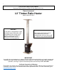
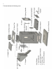
Instructions / Assembly

6
Included in the box is a hardware bag that contains:
Count
Part
Application
32
10/32 x 1/2" Bolts
● Attaching (B) Stove top to (K) Firebox - Uses 12
● (J) Firebox Bottom to (K) Firebox - 9
● (A) Stove top collar to (B) Stove top - 4
● (Y) Top Reflector to (X) Stove Pipe Spark Arrestor – 3
● (L) Door Mounting Bracket to (K) Firebox - 2
4
1/4 x 1/2” Bolts
● (XZ) Base to (K) Firebox - 4
6
¼ x 7/8” Bolts
● (Q) and (Q1) handles to (F) hopper and (O) ashpan - 2 for each
handle. 2 for wheel kit that attaches to the stainless base.
7
10/32” Nuts
● (A) Stove top collar to (B) Stove top - 4
● (Y) Top Reflector to (X) Stove Pipe Spark Arrestor - 3
4
1/4” Nuts
● (Q) and (Q1) handles to (F) hopper and (O) ashpan - 2 for each
handle
10
Lock Washers
● (XZ) Base to (K) Firebox - 4
● (Q) and (Q1) handles to (F) hopper and (O) ashpan - 2 for each
handle
● 2 for wheel kit
2
Spring Handles
● (R) Door Spring Handle and (S) Damper Spring Handle
4
Feet Glides
● (V) Feet Glides to (XZ) Base – 4
9
Self Tapping
Screws
● Self tapping screws are included to secure the stove pipe. Secure
using 3 screws in each pipe section. (Optional)
1.2 Assembly Instructions
Step 1 - Attach Stove Base: Attach wheel kit to base with (2) ¼ 20 x 7/8 bolts and (2) ¼” lock
washers. Lay (K) firebox upside down on a piece of foam provided. Align (XZ) Base holes with the
underside of the firebox (wheels in the rear). Place one lock washer on each ¼ x 1/2’’ bolt and screw
the bolts into the threaded holes of the firebox. Screw In the four feet glides using (4) 5/16” lock
washers to the bottom corners of the base. If you purchased casters, screw in place of the glides with
the large lock-washers provided. Return stove to the upright position.
Step 2 - Installing the Fire Pot and the Fire Box Bottom Plate: The (J) Firebox Bottom is installed,
with the flat surface facing up (½” flanges face down), inside of (K) Firebox. The side of the Firebox
Bottom with 3 threaded holes faces the front of the stove. Attach the Firebox bottom using 9 10/32”
bolts inserted through slotted holes that are located just below the damper (N). The slotted holes are
on all four sides of the firebox. Insert the Firepot into the square cutout on the firebox bottom with
slanted side towards rear of the firebox. For maximum heat output, move the bolts to the lowest
position within the slotted holes on all four sides of the firebox (this allows more fuel in). For use
above 3,000 Ft. in elevation be sure firebox bottom is setting at the lowest position.