
Installation Guide

(continued)
W10712331 A
— 6 —
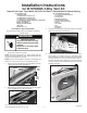
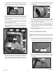
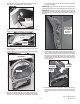
3. Using a cold chisel and hammer around the knockout hole
edge, work around the edge until the knockout is removed.
Use a le to remove the small edge burrs generated by the
knockout procedure.
4. Attach the 229 mm (9.0”) long vent to the blower housing
using the 3/8” long screw removed in step 13 of “Procedure
for Dryer Disassembly” section.
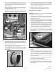
5. Assemble the 305 mm (12.0”) long vent tube and elbow from
kit together using clamp included in kit. Tighten clamp to hold
sub assembly together. See Figure 25.
Side Panel
figure 25
VENT TUBE
(9.0” LONG)
ELBOW
SCREW
(0.375” LONG)
BLOWER
VENT TUBE
(12.0” LONG)
(2) CLAMPS
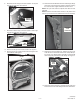
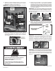
6. Feed this vent tube sub-assembly into the dryer and out the
right side panel exhaust hole. Use clamp included with kit,
slide it onto the elbow and press the elbow onto the 229 mm
(9.0”) vent tube. See Figure 25.
7. Assure the positioning of the exhaust vent assembly and
securely tighten both clamps. See Figure 25.
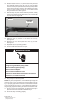
8. From the outside of the dryer, install the vent ring included
with kit by sliding over exhaust vent tube and snap into place.
See Figure 26.
figure 26
VENT RING
POSITIVE
STOP BUMP
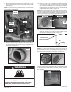
9. Assure the positioning of the exhaust vent assembly, making
sure the positive stop bump on the 305 mm (12.0”) long vent
tube is on the outside of the dryer. See Figure 26. Securely
tighten both clamps. See Figure 25.
10. Right side venting of your dryer is now complete.
11. Proceed to “Completing Dryer Installation” section.
Completing Dryer Installation
IMPORTANT: Take special note of specic areas listed below
assuring proper re-assembly of dryer.
1. Reassemble dryer in reverse order as the dryer was disas-
sembled referencing previous instruction photographs and
following the steps below.
2. Slide the drum and drum belt making sure the drum is sitting
on the rear drum support rollers (Figure 10) and the belt is
not catching anything underneath.
3. When reattaching drum belt, verify belt grooves are toward
the drum outer surface. Lift up on the idler pulley arm and loop
the belt into position as shown in Figure 9. Slowly release the
idler arm putting tension on the belt. Slightly lift up on drum
front and slowly rotate to verify belt is seated correctly.
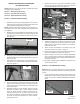
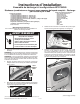
4. When swinging the front bulkhead and lint duct assembly
to the dryer front, be aware that the lint duct bottom edge
clears and resides inside the front lip of the base panel.
See Figure 27.
figure 27
LINT DUCT
LOWER EDGE
BASE PANEL
FRONT LIP
5. Hang the front bulkhead by its two (2) hooks as shown in
Figure 8.
6. Seat the front bulkhead rollers up under the drum lip by
pressing on the bottom edge of the bulkhead door opening
with one hand while turning the drum clockwise with your
other hand. Verify they are seated and the drum felt seals
are not rolled over. Reattach four (4) screws in the bulkhead
corners. See Figure 7.
7. Reattach two (2) screws in the lint duct and reconnect the
moisture strip connector. See Figure 6.
8. Reconnect the drum light connector. See Figure 5.
9. Re-hang the front panel and door assembly to the front of the
dryer (See Figure 4) and connect the door switch connector
(See Figure 3).