
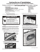
Installation Guide

— 5 —
(continued)
W10712331 A
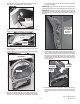
6. Insert the sub-assembly from Step #5 into the left side
knockout hole, rib-end facing out. Slide a clamp onto the
elbow and attach elbow end to the 229 mm (9.0”) vent tube
already in the dryer, attached to the blower. See Figure 21.
figure 22
VENT RING
POSITIVE
STOP BUMP
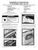
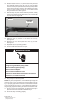
7. From the outside of the dryer, install the vent ring included
with kit by sliding over exhaust vent tube and snap into place.
See Figure 22.
8. Assure the positioning of the exhaust vent assembly, making
sure the positive stop bump on the 305 mm (12.0”) long vent
tube is on the outside of the dryer. See Figure 22. Securely
tighten both clamps. See Figure 21.
9. Left side venting of your dryer is now complete. Reassemble
dryer in reverse order as the dryer was disassembled refer-
encing this instruction sheet assuring proper assembly and
wire lead connections.
10. Proceed to “Completing Dryer Installation” section at the end
of this instruction sheet.
Section 3 - Right Side Exhaust Venting
NOTE: Allow for a min. clearance of 10” from wall to dryer side
panel if venting exhaust downward after existing side panel of
dryer.
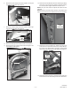
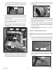
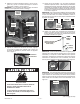
1. As you are facing the dryer, review the lower section of the
right side panel. If two (2) knockout features are present
(Figure 23) remove the REAR MOST KNOCKOUT ONLY.
2. Remove the most REAR MOST right side knockout by using
either a 1/8” drill bit and drill or a cold chisel and hammer.
Remove the six (6) knockout retaining tabs around the edge.
See Figure 24.
Side Panel
figure 23
DRYER
FRONT
MOST REARWARD
KNOCKOUT
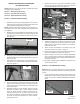
2. To remove the most rearward left side knockout, use either
a 1/8” drill bit and drill or a cold chisel and hammer. Re-
move the six(6) knockout retaining tabs around the edge.
See Figure 20.
SIDE PANEL
KNOCKOUT
figure 20
3. Using a cold chisel and hammer around the knockout hole
edge, work around the edge until the knockout is removed.
Use a le to remove the small edge burrs generated by the
knockout procedure.
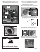
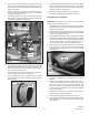
4. Attach the 229 mm (9.0”) long vent to the blower housing
using the 3/8” long screw removed in step 13 of “Procedure
for Dryer Disassembly” section.
5. Attach the 305 mm (12.0”) long vent tube, the 86 mm
(3.40”), and elbow from kit together using clamps in-
cluded in kit. Tighten clamp to hold sub assembly together.
See Figure 21.
figure 24
SIDE PANEL
KNOCKOUT
VENT TUBE
(9.0” LONG)
ELBOW
SCREW
(0.375” LONG)
BLOWER
figure 21
(3) CLAMPS
VENT TUBE
(3.40” LONG)
VENT TUBE
(12.0” LONG)