
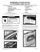
Installation Guide
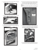
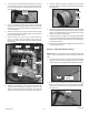
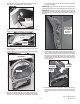

13. Remove the existing exhaust vent by removing one (1) 3/8”
long screw that secures the vent to the blower housing outlet.
See Figure 10.
NOTE: The screw (3/8” long) removed in step 13 must be used
in this location for reassembly.
— 3 —
(continued)
W10712331 A
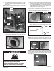
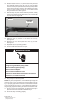
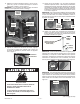
15. Plug the 4” hole in the rear panel that the existing exhaust
vent ran through using the metal cover plate included with
kit. Use screw included with kit to secure plate in position.
Install plate from the inside of the dryer rear panel with tab
of plate positioned as shown in Figure 12.
NOTE: As recommended, install cover plate from the inside of
the dryer with tab located at the bottom of the rear exhaust hole.
To aid in installation, take a screwdriver, inserting it into the larger
hole in the cover plate and pulling the plate toward the rear.
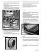
14. Remove the vent ring by depressing the three (3) tabs on
the ring (See Figure 10) and push ring out away from dryer
rear panel. See Figure 11.
figure 10 (electric dryer shown)
Bottom Panel
(3) DRUM
SUPPORT
ROLLERS
3/8” LONG
SCREW
BLOWER
EXISTING
VENT RING
TAB
Fire Hazard
Install cabinet plug(s) before operating.
Failure to follow these instructions can result in
death, fire, electrical shock, or serious injury.
WARNING
figure 12
Bottom Panel
Bottom Panel
OUTSIDE VIEW
INSIDE VIEW
(1) SCREW
TAB-PLATE
COVER
PLATE
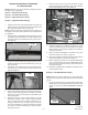
16. Use screw included with kit to secure plate in position by
driving the retaining screw into the plate’s smaller hole to
lock the plate in position as shown in Figure 13.
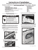
NOTE: If unit was previously setup for side venting leaving an
exposed knock-out hole, or had additional panel knock-outs re-
moved, from outside of dryer install the plastic plug(s) included
with kit to the side panel knock-out hole(s). See Figure 14.
figure 11
Bottom Panel
VENT RING
NOTE: If unit was previously setup for bottom venting, from inside
of dryer install the metal cover plate with screw included with kit
to the bottom panel hole that the vent tube previously existed.
See Figure 15.
figure 13
Bottom Panel
CABINET
REAR
TAB
BOTTOM
OF DRYER
AGAINST EDGE OF CABINET)
figure 14
Bottom Panel
Bottom Panel
(3) TABS
figure 15
Bottom Panel
COVER
PLATE
(1) SCREW