
Installation Guide

9
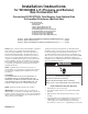
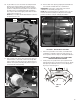
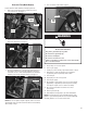
Pressure Test (Both Styles)
Check minimum and maximum inlet gas pressure:
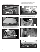
1. Remove pressure tap plug from valve body using a
3/16" hex wrench. See Figure 1.
FIGURE 1
(3/16") HEX
WRENCH
GAS VALVE
ASSEMBLY
PRESSURE
TAP PLUG
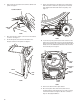
2. Insert pressure tap and nger-tighten. Remove view hole
plug from side panel. See Figure 2.
FIGURE 2
VIEW
HOLE
PLUG
PRESSURE
TAP
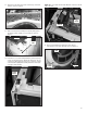
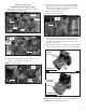
3. Connect a airtight hose to pressure tap and run the hose
through the view hole on the right side panel. Connect
other end of hose to manometer (Airtight hose will attach
between pressure tap and manometer.) See Figure 3.
FIGURE 3
MANOMETER
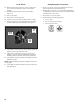
NOTE: Be sure to replace all parts a panels, and to reconnect
all wire leads and connections that were disconnected during
disassembly of dryer.
FIGURE 4
MANOMETER
FRONT
PANEL
4. Turn on and zero manometer. Figure 4.
5. Plug in dryer or reconnect power.
6. Turn on gas supply.
7. Set dryer cycle to time dry, high heat and turn on dryer.
8. After ignition, verify gas inlet pressure is between
8" (203 mm) and 13" (330 mm) water column.
9. Turn off dryer.
10. Unplug dryer or disconnect power.
11. Turn off gas supply.
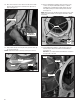
12. Disassemble control panel or top & console assembly
(depending on application) and front panel assembly
from dryer to regain access to burner assembly.
13. Disconnect manometer and remove hose from
pressure tap.
14. Remove pressure tap.
15. Reinstall pressure tap plug to gas valve and tighten.
NOTE: Pressure tap plug can be reinstalled and securely
tighten to gas valve body without removal of the bulkhead
assembly with the use of a 3/16" hex wrench.
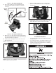
Electrical Shock Hazard
Plug into a grounded 3 prong outlet.
Do not remove ground prong.
Do not use an adapter.
Do not use an extension cord.
Failure to follow these instructions can result in death,
re, or electrical shock.
WARNING