
Installation Guide

Page
4
Unirac Code-Compliant Installation Manual
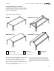
SunFrame
R
1411 Broadway Boulevard NE
Albuquerque NM 87102-1545 USA
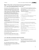
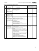
Miles per hour
(meters per second)
Figure 1. Basic Wind Speeds. Adapted and
applicable to ASCE 7-05. Values are nominal
design 3-second gust wind speeds at 33 feet
above ground for Exposure Category C.
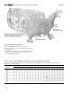
10 3 3 3 3 3 4 4 4 4 4 4 4 5 6 7 8 12 16 20
15 3 3 3 3 3 4 5 6 6 6 6 6 6 6 7 8 12 16 20
20 3 3 3 3 3 4 5 6 7 8 8 8 8 8 8 8 12 16 20
25 3 3 3 3 3 4 5 6 7 8 9 10 10 10 10 10 12 16 20
30 3 3 3 3 3 4 5 6 7 8 9 10 12 12 12 12 12 16 20
35 3 3 3 3 3 4 5 6 7 8 9 10 12.5 14 14 14 14 16 20
40 3 3 3 3 3 4 5 6 7 8 9 10 12.5 15 16 16 16 16 20
45 3 3 3 3 3 4 5 6 7 8 9 10 12.5 15 17.5 18 18 18 20
50 3 3 3 3 3 4 5 6 7 8 9 10 12.5 15 17.5 20 20 20 20
60 3 3 3 3 3 4 5 6 7 8 9 10 12.5 15 17.5 20 24 24 24
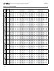
Roof Least Horizontal Dimension (ft)
Height (ft)
10 15 20 25 30 40 50 60 70 80 90 100 125 150 175 200 300 400 500
Table 1. Determine Roof/Wall Zone, length (a) according to building width and height
a = 10 percent of the least horizontal dimension or 0.4h, whichever is smaller, but not less than either 4% of the least horizontal
dimension or 3 ft of the building.
Source: ASCE/SEI 7-05, Minimum Design Loads for Buildings and Other Structures, Chapter 6, Figure 6-3, p. 41.
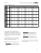
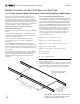
Step 3: Determine Roof/Wall Zone:
The Design Wind Load will vary based on where the
installation is located on a roof. Arrays may be located in more
than one roof zone.
Using Table 1, determine the Roof Zone Setback Length, a (ft),
according to the width and height of the building on which
you are installing the pv system.