
Installation Guide

Page
21
SunFrame
Unirac Code-Compliant Installation Manual
R
1411 Broadway Boulevard NE
Albuquerque NM 87102-1545 USA
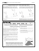
8. Installing the remaining modules row by row:
Repeat Steps 6 and 7 for the remaining rows (Fig. 15). Each
subsequent cap strip will secure the tops to the modules being
installed and the bottoms of the modules in the row above.
Place the final cap strip in the lowest rail, securing the bottom
of the lowest module row.
6. Securing the first module:
Gather sufficient lengths of cap strip
to cover the length of the first rail. For
maximum visual appeal and material
conservation see “Material planning for
rails and cap strips” (p. 20).
Slide the first module into final position
at one end of the array. Lay the remaining
modules in the top row, leaving a gap
about a foot wide between the first and
second modules (Fig. 13).
The temporary gap allows the installer to
place one of his feet between modules. He
can access the section of the cap strip he
needs to secure while leaning toward the
peak of the roof. For the time being, the
last module may overhang the rail by up
to one third its width.
Attach the end of the cap strip with
the cap strip screws (Fig. 13, inset), so
that the upper end of the first module is
secure.
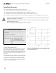
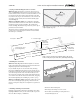
Figure 13. Begin cap strip installation.
Cap strip screws
Stepping gap
Permissable overhang:
1/3 module width
Do not install second
cap strip until lower
modules are placed
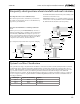
7. Installing the remaining modules in the top row:
Slide the next module into final position and install the screws
to secure it (Fig. 14). For a neat installation, use cable ties to
attach excess wiring to the rail beneath the flanges. Unirac’s
cable ties can be attached to the SunFrame rail by drilling a
¼-inch hole in the rail and pushing the end of the tie into the
hole.
Continue the process until all modules in the top row are in
final place and secured from the top. When complete, every
prepunched hole in the cap strip will be secured by a screw,
and the top end of the first row of modules will be secure.
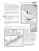
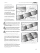
1. Slide
2. Install screws
Figure 14. Position and secure modules one by one.
Stepping gap
Figure 15. As modules slide into place, the stepping gap shifts,
always allowing access to the section of cap strip being secured.
Secured
1st module
Slide and secure
one by one
Stepping gap
The structural integrity of your array requires that cap
strip screws fully engage the threaded rail. Use the cap
strip screws supplied with your cap strips. Any substitute
screws must be ¼-20 Type F thread cutting (18-8 stainless
steel) and the correct length.
Every cap strip segment must have a cap strip screw 4
inches or less from each end. If the nearest predrilled
hole falls more than 4 inches from any end, drill a
¼-inch hole 2 inches from the end and install an additional
screw.
Wherever it is necessary to make a new cap strip hole,
drill a ¼-inch hole before installing the cap strip screw.