
Installation Guide

Page
19
SunFrame
Unirac Code-Compliant Installation Manual
R
1411 Broadway Boulevard NE
Albuquerque NM 87102-1545 USA
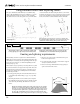
4. Installing the second rail:
With L-feet only (Fig. 12): Install and align the second rail
in the same manner and orientation as the first rail. After rail
alignment, tighten the rail mounting bolts.
Lay one module in place at one end of the rails, and snug
the upper rail (Fig. 12) toward the lower rail, leaving no gap
between the ends of the modules and either rail. (If pan-head
screw heads represent the true end of the modules, be sure
the screw heads touch the rails on both ends.) Tighten the lag
screw on that end. Slide the module down the rails, snugging
the rails and tightening the remaining lag screws as you go.
With L-foot adjusting sliders: Install rails on first and second
rows of L-feet. Verify spacing by placing a module onto the
rails at several points along the row. Adjust L-foot positions as
needed.
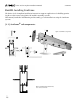
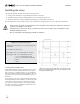
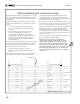
Figure 10. L-foot separation. See the note on module length in the
caption of Figure 3 (p. 10).
3. Laying out and installing the next row of L-feet:
With L-feet only: Position the second row of L-feet in accor-
dance with Figure 10. Ensure that you measure between the
lower bolt hole centers of each row of L-feet. Install the second
row of L-feet in the same manner and orientation as the first
row, but leave the lag screws a half turn loose. Be aware of the
set-up time of your sealant; the L-feet will not be fully tight-
ened until Step. 4.
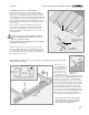
With L-foot adjusting sliders: Use a chalk line to mark the
position of the slider center holes of the next row. The illustra-
tion below provides spacing guidelines. The length of the
module (A in Fig. 11) includes any protrusions, such as lips or
pan-head screws in its frame.
Attach and seal L-foot adjusting slider: Install lower lag first,
footing bolt next, and upper lag last. Attach an L-foot with its
short side up to each slider.
Module length + ¾˝
(hole to hole)
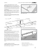
Figure 12. Position and secure top rail.
Module
Lag screw
(half turn loose)
Lag screw
(tight)
Snug
Roof peak
A = module length
A
A + 2
1
/4
”
A +
3
/4
”
A + 1
3
/16
”
A - 3
1
/4
”
Lowest row of L-feet
(no footing sliders)
Figure 11. If you are using L-foot adjusting sliders, this spacing
between rows places L-feet at the center of their adjustment range.
Align slider
center hole
to chalk line
Align slider
center hole
to chalk line
A
5. Installing remaining L-feet and rails:
Install the L-feet and the rails for the remaining rows, follow-
ing Steps 3 and 4. You may use the same module to space all
the rows. When complete, confirm that:
• All rails are fitted and aligned.
• All footing bolts and lag screws are secure.
• The module used for fitting is resting (but not se-
cured) in the highest row.