
Installation Guide

Page
18
Unirac Code-Compliant Installation Manual
SunFrame
R
1411 Broadway Boulevard NE
Albuquerque NM 87102-1545 USA
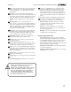
If the standoff supporting the lowest rail is 1 inch taller than
the standoffs on the footing sliders, place both L-feet in the same
orientation—either both long side up or both short side up.
With standoffs of equal length, orient L-foot to compensate for
height difference.
Footing and splicing requirements
The following criteria are required for sound installations.
While short sections of rail are structurally permissible, they
can usually be avoided by effective planning, which also pro-
motes superior aesthetics. See “Material planning for rails
and cap strips” (p. 20).
The installer is solely responsible for ensuring that the roof and
its structural members can support the array and its live loads.
A thermal break is required every 40 feet of continuously con-
nected rail. See Unirac Splices and Expansion Joints Installa-
tion Manual for details .
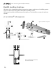
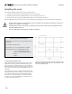
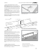
1. Footing spacing along the rail (A in illustration above)
is determined by wind loading (see pp. 2–3, especially
step 1).
2. Overhang (B) must be no more than 1/3 the length of
the maximum footing spacing (A). For example, if Span
(A) is 48 inches, Overhang (B) should not exceed 16
inches.
3. Do not locate a splice in the center third of the span
between two adjacent feet.
4. In a spliced length of rail, all sections must be support-
ed by no less than two L-feet.
5. Rail sections longer than half the footing spacing re-
quire no fewer than two L-feet.
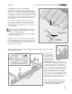
Using standoffs with L-foot adjusting sliders
Two-piece aluminum standoffs may be used with footing
sliders, although flashings may not be available to cover the
entire length of the slider. Use the bases of the standoffs
only in the lowest row. In subsequent rows, attach the shaft
of each standoff to the slider using the slider’s
3
/8-inch hex-
head bolt. Note that L-feet are positioned long side up on the
lowest rows and with long side down in subsequent rows—
in the same manner as an installation with no standoffs.
B
A
L-foot
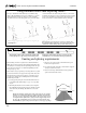
This example assumes a rail seven times the length of the
footing spacing (A). A splice may be located in any of the
shaded areas. If more than one splice is used, be sure the
combination does not violate the following requirements:
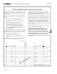
Modules should always be fully supported by rails. In other words, modules
should never overhang rails. This is especially critical when supporting the
short side of a non-rectangular module. When a rail supports a pair of non-
rectangular modules by themselves (right), it must be supported by at least
two L-feet. The rail should be at least 14 and no more than 24 inches long,
which will likely require a stringer between rafters to ensure proper footings.
Non-rectangular modules
Rail
Rafters
Stringer