
Installation Guide

Page
17
SunFrame
Unirac Code-Compliant Installation Manual
R
1411 Broadway Boulevard NE
Albuquerque NM 87102-1545 USA
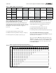
2. Installing the lowest row of L-feet and rail:
In the lowest row, it is not necessary to use L-foot adjust-
ing sliders, even if you plan to use them in subsequent rows.
Install L-feet, in conjunction with proper flashing equipment
and techniques, directly onto low profile roofing material such
as asphalt shingles or sheet metal. (For high profile roofs, such
as tile or shake, use optional standoffs with flashing to raise
L-feet. L-feet must be flush with or above the highest point of
the roof surface.)
L-feet can be placed with the double-slotted side against
the roof surface (as in Fig. 7) or with the single-slotted side
against the roof (which increases air circulation beneath
modules). Module-to-roof dimensions are listed on page 19 for
both arrangements.
If you are using L-foot adjusting sliders, you must use
the short side of the the L-foot against the roof in the
first row. See Figure 9 below.
If you are using both L-foot adjusting sliders and standoffs,
see the upper box on page 18.
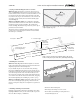
Install the first row of L-feet at the lower edge of the instal-
lation area (Fig. 8). Ensure feet are aligned by using a chalk
line. (A SunFrame rail can also be used as a straight edge.)
Position the L-feet with respect to the lower edge of the roof as
illustrated in Figures 7 and 8.
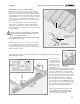
Figure 7. Placement of first L-foot row.
Figure 8. L-Foot
orientation.
Lag
screw
L feet
2¾˝
Lower edge of
installation area
Always lag into slot
nearest the bend in
the L-foot
Roof peak
If the double slotted sides of the L-feet are against the roof, lag through the slot nearest the bend
in the L-foot (Figs. 7 and 8).
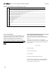
Cut the rails to your
array width, being sure
to keep rail slots free
of roofing grit or other
debris. If your instal-
lation requires splices,
assemble them prior to
attaching L-feet (see “Footing and splicing require-
ments,” p. 18, and “Material planning for rails and
cap strips,” p. 20). Slide the
3
/
8
-inch mounting
bolts into the footing slots. If more than one splice
is used on a rail, slide L-foot bolt(s) into the footing
slot(s) of the interior rail segment(s) before splicing.
Loosely attach the rails to the L-feet with the
flange nuts. Ensure that rails are oriented with re-
spect to the L-feet as shown in Figure 9. Align the
ends of the rail to the edge of the installation area.
Ensure that the rail is straight and parallel to the
edge of the roof. Then tighten the lag screws.
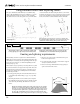
Roof peak
Figure 9. L-foot orientation in conjunction with
L-foot adjusting sliders. The sliders include two
utility slots to secure module wiring, combiner
boxes, and other system components.
Utility slot for
1
/
4
″
hexhead bolt
Slot for
3
/
8
″
footing bolt
Utility slot for No. 10 screw