
Installation Guide

Page
10
Unirac Code-Compliant Installation Manual
SunFrame
R
1411 Broadway Boulevard NE
Albuquerque NM 87102-1545 USA
The procedure to determine the Unirac SunFrame series
rail type and rail span uses standard beam calculations and
structural engineering methodology. The beam calculations
are based on a simply supported beam conservatively, ignoring
the reductions allowed for supports of continuous beams over
multiple supports. Please refer to Part I for more information
on beam calculations, equations and assumptions.
In using this document, obtaining correct results is
dependent upon the following:
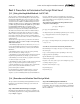
1. Obtain the Snow Load for your area from your local building
official.
2. Obtain the Design Wind Load, p
net
. See Part I (Procedure
to Determine the Design Wind Load) for more information on
calculating the Design Wind Load.
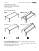
3. Please Note: The terms rail span and footing spacing
are interchangeable in this document. See Figure 3 for
illustrations.
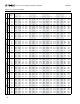
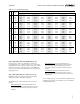
4. To use Table 8a and Table 8b the Dead Load for your
specific installation must be less than 5 psf, including modules
and Unirac racking systems. If the Dead Load is greater than 5
psf, see your Unirac distributor, a local structural engineer or
contact Unirac.
The following procedure will guide you in selecting a Unirac
rail for a flush mount installation. It will also help determine
the design loading imposed by the Unirac PV Mounting
Assembly that the building structure must be capable of
supporting.
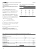
Step 1: Determine the Total Design Load:
The Total Design Load, P (psf) is determined using ASCE 7-05
2.4.1 (ASD Method equations 3,5,6 and 7) by adding the Snow
Load
1
, S (psf), Design Wind Load, p
net
(psf) from Part I, Step
9 and the Dead Load (psf). Both Uplift and Downforce Wind
Loads calculated in Step 9 of Part 2 must be investigated. Use
Table 7 to calculate the Total Design Load for the load cases.
The beam must be sized for uplift, downforce and side loads.
Use the maximum absolute value of the three downforce
cases and and the uplift case to size the beam for uplift and
downforce. Use the side load case to size the beam for side
load. Use the uplift case only for sizing lag bolts pull out
capacities (Part II, Step 6).
P (psf) = 1.0D + 1.0S
1
(downforce case 1)
P (psf) = 1.0D + 1.0
p
net
(downforce case 2)
P (psf) = 1.0D + 0.75S
1
+ 0.75p
net
(downforce case 3)
P (psf) = 0.6D + 1.0
p
net
(uplift)
P (psf) = sin(roof angle)D + sin(roof angle)S
(side)
D = Dead Load (psf)
S = Snow Load (psf)
p
net
= Design Wind Load (psf)
The maximum Dead Load, D (psf), is 5 psf based on market
research and internal data.
1
Snow Load Reduction - The snow load can be reduced according
to Chapter 7 of ASCE 7-05. The reduction is a function of the roof
slope, Exposure Factor, Importance Factor and Thermal Factor.
Please refer to Chapter 7 of ASCE 7-05 for more information.
Part II. Procedure to Select Rail Span and Rail Type
[2.1.] Using Standard Beam Calculations, Structural Engineering Methodology:
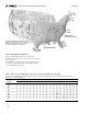
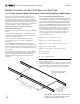
Note: Modules must be centered symmetrically on
the rails (+/- 2*), as shown in Figure 3. If this is
not the case, call Unirac for assistance.
B
L
Module length
perpendicular to
rails
Rail Span or Foot Spacing
Figure 3. Rail span and footing
spacing are interchangeable.