
Manual

Diagnostics
e diagnostics function allows the user to monitor Radio Link status, check the rmware version, trouble-
shoot stations using the Sequence Stations options, monitor the system’s water usage, monitor all system’s sensor
status, monitor system’s voltages, check alarm status, clear alarms and execute a self diagnostics to the system.
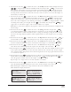
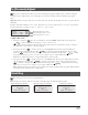
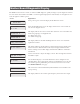
Menu: Clear Alarms
Press START to clear
alarms for all Sta s
Menu: Station Alarms
S001 Alarms: 01
No Comm w/ Decoder
06/15/11, 10:07
Use this menu to clear alarm
codes once it’s been restored.
Use this menu to check
alarm codes that have been
activated. Use the codes to
troubleshoot for possible
errors and faults.
,
Checking and Clearing Alarms
Press the down arrow key to advance the cursor to the S001: field. Use the input dial to scroll
through all the stations with alarms. To clear the alarm, press the right arrow key to the Alarm: field, use the
Input Dial to display Clear Alarm. Press the down arrow key to execute.
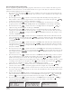
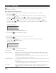
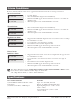
Menu: Revision
Revision: 02.08
Rev. Date 01/04/11
Menu: RunDiagnostics
Perform: Comm Check
Press START to start
Use this menu to
verify firmware
version.
Use this menu perform a
Comm (Communication)
Check or a Solenoid Chk
(check).
Menu: PowerUp Detect
Capacity: 200 sta s
PD 06/28/11 13:53:51
PU 06/29/11 11:15:32
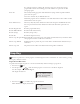
Menu: VA Monitor
Battery Volt: 3.3
LCD Voltage: 2.7
Board temp: 28c
Use this menu to monitor the
system’s voltages.
This menu will display
the detected station
capacity from the last
Power Down (PD).
PU will display the date
and time of the last
Power Up.
,
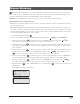
Total Timeouts: 001
Total Failed: 002
Clear Total: No
Menu: Link Monitor
Sent: GetPumpPress
Resp: 2nd
Total Bad Resp: 001
Menu: Event Codes
Clear log: No
Last code: 93
06/30/11 10:21:46
This menu will display the last
logged event that may help
diagnose problems. The event
code, date and time the event
occurred will be displayed. Clear
the log by navigating to “Clear
log: No” using the Right or Left
arrows .
Use the input dial to toggle No
to Yes. Press the Up or Down
arrow to accept.
Use this menu to display
when and what messages
are sent.
1st Line: Name of the sent message
2nd Line: Response status
3rd Line: Number of messages that were sent out with bad responses
4th Line: Number of messages that did not get a response
5th Line: Number of messages that failed to communicate after
Use the arrow keys to navigate to Clear Total and toggle
No to Yes to clear all Link Monitor’s values.
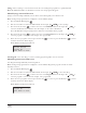
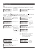
Sample Alarm Display During Normal Operation:
18
Tue 08/07/12 02:24pm
Sec: 54
LowPres
Day Change: 12:00am
“LowPres” indicates a low-
pressure alarm.
Press DOWN to list
07/03/11, 11:05
Station OPEN
No comm w/ decoder
Sun 07/03/11 11:04am
Chk Alarms Sec: 36
Next start: 07:00pm
TDC indicates Check
Alarms Status when a fault is
detected within the system.
Station Alarms will
list any detected
system faults
with descriptions
for quick and
easy system
troubleshooting.