
User Manual


Pg. 7
Operation and Setup
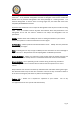
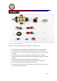
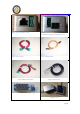
Figure 2 Items Included in Motor Kit
Please refer to Figure 2 above and figures 4 through 11 on pages 9 and 10.
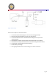
1. Connect one end of the RJ45 black data cable (provided) to the motor receptacle
2. Connect the other end of the RJ45 data cable to the ECU. See below diagram.
3. Connect one end of the servo cable (provided) between the ECU port labeled
“Throttle”
4. Connect the other end of the JR cable to the receiver throttle port (usually #3)
5. Connect the Battery cable (provided) to ECU port labeled battery/pump (see below
diagram).
6. Connect the pump to the deans connector on the battery cable
7. Connect the motor power cable (provided) to the motor port as shown below.
8. Connect the other end of the motor cable to the ECU port.
9. Connect the GSU to the ECU port labeled GSU. Observe correct polarity or the
terminal will not operate properly.