SWIWIN Turbines SW Series Kero Start Full Autostart with Auto-Restart Operations Manual
Table of Contents Introduction ...................................................................................................................................... 3 Safety First ....................................................................................................................... 3 Warning to Bystanders ..................................................................................................... 3 Fire extinguishers ...............................................................
Test function menu ................................................................................................................. 15 Data chart................................................................................................................................ 16 Specifications .................................................................................................................................. 17 SW 60 ..............................................................................
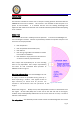
Introduction This manual is intended to aid the user in setup and running practices associated with the SWIWIN SW series micro turbines. This manual is not intended to take the place of a primer on micro-turbines. It is assumed that the user has working knowledge and experience with turbines and that each user is familiar with best practices before attempting to run a turbine. Safety First Users need to be versed in model jet turbine operation. Purchaser acknowledges the risks and dangers involved.
ABC extinguisher on hand at all times. CO2 is the only recommended application for a motor fire. A dry chemical extinguisher will work to extinguish a fire but the residue left behind from dry chemical extinguishers does heavy damage to a running turbine. If a chemical extinguisher is used to douse a running engine fire, the motor will need to be completely dissembled and cleaned. Important Note: Please be sure to inspect all extinguishers each day that a turbine is being used.
SWIWIN Limited Lifetime Warranty SWIWIN warrants each turbine to be free from defects in materials and workmanship during normal usage, according to the following terms and conditions. 1. The warranty is transferable to any subsequent user. There is a $50 admin fee which will be collected when ownership of the motor is transferred. Please make sure that each user registers the motor with SWIWIN at the time of transfer so that service can be maintained on the motor. 2.
4. Buyer is required to register the motor with SWIWIN at the time of purchase. Please retain all receipts and paper work. 5. Buyer agrees to cover the cost of shipping the turbine to SWIWIN USA for repair. Exclusions 6. Warranty and/or extended coverage does not apply under the following circumstances: a. The turbine is used for commercial or institutional (school) use b. The turbine has been stored improperly c. The turbine was submerged in water d. The turbine has been modified in any fashion e.
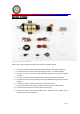
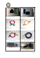
Operation and Setup Figure 2 Items Included in Motor Kit Please refer to Figure 2 above and figures 4 through 11 on pages 9 and 10. 1. Connect one end of the RJ45 black data cable (provided) to the motor receptacle 2. Connect the other end of the RJ45 data cable to the ECU. See below diagram. 3. Connect one end of the servo cable (provided) between the ECU port labeled “Throttle” 4. Connect the other end of the JR cable to the receiver throttle port (usually #3) 5.
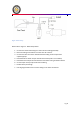
Figure 3 Motor Setup Please refer to Figure 3 - Motor Setup above 1. Connect the motor festo fitting to a section of 4mm tubing (included). 2. Route the tubing to the filter then to the shut off as shown. 3. Connect the other end of the shutoff with 4mm tubing to the output of the supertrap pump. 4. Plumb the UAT as shown and per the UAT instructions (UAT is not included) 5. Plumb the Fuel tank per the manufacturer instructions noting orientation above. 6.
Figure 4 Power and Sensor Cable Figure 5 Battery/pump cable and throttle cable Figure 6 Power Cable Figure 8 Batt & Pump cable Figure 7 Throttle Cable Figure 9 Sensor Cable Figure 10 Rpm Display(optional) Figure 11 GSU Pg.
ECU The SWIWIN ECU was designed from the ground up and is based on 32 bit microprocessor functionality and designed specifically for SWIWIN Turbines. The ECU offers the following benefits: Data Logging Auto start Automatic Restart Color Screen visible in direct sunlight Configurable thrust curve with very fast throttle response ECU/Motor Electrical Connections Do not exceed these voltages! Receiver voltage:5-8.4V(5S Nimh or 2S Life or 2S Lipo) Power voltage:9.9-11.
Initial Screen RPM – Current running status of the turbine Temp – Current temperature of engine Curr – Electrical current in use Cap – Main Battery that has been used ACC – Response time from idle to max. in seconds. Screen Bottom – Running Status RPM - 0 – 100% Temp - 0 – 1000 Celsius Pump – output measured in volts – ex. 4300/1000 = 4.
Main Menu – Display all Parameter Screen Same as last screen with these additional functions Starter – set starter parameters Calibrate fuel – secondary screen for fuel parameters(factory setting) Start Up Screen (advanced functions) PumpVoltage – Pump start voltage – begin with this value and increase according to ramp value. GlowPlug – Set Glow Plug starting voltage. PumpVoltage - Set pump voltage Typical value is .
GasValve and MainValve - Set the percentage of time of the main fuel valve is open at beginning of the switchover phase. This percentage will increase automatically with RPM until arrive to fully open when the RPM of next phase are reached. The time where the burner valve is open is complementary to the injector time, so when the main valve is open at 80%, the burner is 20%.
Cooling Sets the cooling rpm after shut down or when starter is manually run using test functions. *Please note that following a failsafe failure or flameout that the motor will not automatically enter a cool down sequence. This is because the ECU has no way of knowing the status of the motor whether flame out, crash or other.
RPM Acceleration Curve/Delay time Set FULL (high speed) - The ECU will automatically calculate the response of IDLE the acceleration rate of value (low speed). Adjust according to weather, Altitude (ASL) or other conditions which require adjustments to delay time. It is best to select a value that is lower than a setting that yields the fastest possible response time in order to avoid a flame out. IDLE change low rpm acceleration.
Data chart Record running data use the increment and decrement key to step through events in the data chart. The color corresponding parameter as follows to each Red – Temp Yellow – Throttle position light blue – Pump Green – RPM Dark Blue - Power Pg.
Specifications SW 60 Thrust RPM Range EGT Fuel Consumption @ 83% power Fuel Lubrication Start Restart Weight Diameter Length Maintenance Interval Metric US 6kg 13.2lbs 50,000 - 160,000 400 - 550 C 750 - 1025F 181ml 6.12 oz kero or diesel 5% kero, 3% diesel full autostart auto restart 800 g 1.76 lb 83mm 3 1/4" 226mm 8 5/16" 25 hours SW 120 Thrust RPM Range EGT Fuel Consumption @ 83% power Fuel Lubrication Start Restart Weight Diameter Length Maintenance Interval Metric US 12kg 26.
SW 140 Thrust RPM Range EGT Fuel Consumption @ 83% power Fuel Lubrication Start Restart Weight Diameter Length Maintenance Interval Metric US 14kg 30.86 lb 38,000 - 128,000 700 C 1292F 380ml 12.84oz kero or diesel 5% kero, 3% diesel full autostart auto restart 1.4kg 2.73lb 102mm 4" 283mm 11 1/8" 25 hours Figure 12 SW 60 Dimensions Pg.
Figure 13 SW 120/140 Dimensions Pg.
INDEX Cooling ..................................................................................................................................... 16 Data chart ................................................................................................................................ 18 Diagram of Components............................................................................................................ 7 Ear Protection .......................................................................