
User Manual

Smart Machine Smart Decision
SIM7100_Hardware_Design_V1.02 2015-06-16
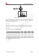
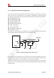
Figure 34: Antenna matching circuit (AUX_ANT)
In above figure, R3, C3, C4 and R4 are used for auxiliary antenna matching. By default, the R3, R4
are 0Ωresistors, and the C3, C4 are reserved for tuning.
Note
:
SIMCom suggests the LTE auxiliary antenna to be kept on, since there are many high
bands in the designing of TDD-LTE, such as band38, band40 and band41. Because of the high
insert loss of the RF cable and layout lines, the receiver sensitivity of these bands above will have
risk to meet the authentication without the diversity antenna. For more details about auxiliary
antenna design notice, please refer to document [26].
4.3 GNSS (GPS and GLONASS)
SIM7100 merges GNSS (GPS/GLONASS) satellite and network information to provide a
high-availability solution that offers industry-leading accuracy and performance. This solution
performs well, even in very challenging environmental conditions where conventional GNSS
receivers fail, and provides a platform to enable wireless operators to address both location-based
services and emergency mandates.
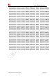
4.3.1 GNSS Technical specification
l Tracking sensitivity: -159 dBm(GPS)/-158 dBm(GLONASS)
l Cold-start sensitivity: -148 dBm
l Accuracy (Open Sky): 2.5m (CEP50)
l TTFF (Open Sky) : Hot start <1s, Cold start<35s
l Receiver Type: 16-channel, C/A Code
l GPS L1 Frequency: 1575.42±1.023MHz
l GLONASS: 1597.5~1605.8 MHz
l Update rate: Default 1 Hz
l GNSS data format: NMEA-0183
l GNSS Current consumption : 100mA ((WCDMA/GSM Sleep ,in total on VBAT pins)
l GNSS antenna: Passive/Active antenna