
User Manual

Smart Machine Smart Decision
SIM7100_Hardware_Design_V1.02 2015-06-16
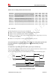
Table 9: Power off timing and Electronic Characteristic
Symbol Parameter
Time value
Min. Typ.
Max.
Unit
T
off
The active low level time pulse on PWRKEY pin to
power off module
2.5 -- -- s
T
off(status)
The time from power-off issue to STATUS pin output
low level(indicating power off )*
10 - - s
T
off(uart)
The time from power-off issue to UART port off 10 - - s
T
off-on
The buffer time from power-off issue to power-on
issue
0 - - s
V
IH
Input high level voltage on PWRKEY pin 1.17 1.8 2.1 V
V
IL
Input low level voltage on PWRKEY pin -0.3 0 0.3 V
*Note: The STATUS pin can be used to detect whether module is powered on or not. When
module has been powered on and firmware goes ready, STATUS will be high level, or else
STATUS will still low level.
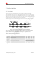
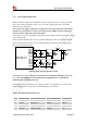
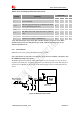
3.2.3 Reset Function
SIM7100 can be reset by pulling the RESET pin down to ground.
Note: This function is only used as an emergency reset, when AT command “AT+CPOF” and
the PWRKEY pin all have lost efficacy.
The RESET pin has been pulled up with a 40KΩ resistor to 1.8V internally, so it does not need to
be pulled up externally. It is strongly recommended to put a100nF capacitor and an ESD protection
diode close to the RESET pin. Please refer to the following figure for the recommended reference
circuit.
Figure 14: Reference Reset Circuit