
User Manual

Smart Machine Smart Decision
SIM7100_Hardware_Design_V1.02 2015-06-16
3.1.1 Power supply Design Guide
Make sure that the voltage on the VBAT pins will never drop below 3.4V even during a transmit
burst, when current consumption may rise up to 2A. If the voltage drops below 3.4V, the RF
performance may be affected.
Note: If the power supply for BAT pins can support up to 2A, using a total of more than 300uF
capacitors is recommended, or else users must using a total of 1000uF capacitors typically, in
order to avoid the voltage drop is more than 300mV..
Some multi-layer ceramic chip (MLCC) capacitors (0.1/1uF) with low ESR in high frequency band
can be used for EMC.
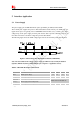
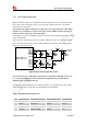
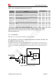
These capacitors should be put as close as possible to VBAT pads. Also User should keep VBAT
trace on circuit board wider than 2 mm to minimize PCB trace impedance. The following figure
shows the recommended circuit.
Figure 8: Power Supply Application Circuit
Note: The Cd, Ce, Cb, Cc and Cf are recommended to be mounted for SIM7100, or the Ca, Cb,
Ce, Cc and Cf for SIM5360. For more details about compatibility between SIM7100 and
SIM5360, please refer to document [25].
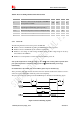
In addition, in order to guarding for over voltage protection, it is suggested to use a zener diode
with 5.1V reverse zener voltage and more than 500mW power dissipation.
Table 7: Recommended Zener Diode List
No. Manufacturer
Part Number power dissipation Package
1 On semi MMSZ5231BT1G 500mW SOD123
2 Prisemi PZ3D4V2H 500mW SOD323
3 Vishay MMSZ4689-V 500mW SOD123
4 Crownpo CDZ55C5V1SM 500mW 0805