
User Manual

Smart Machine Smart Decision
SIM7100_Hardware_Design_V1.02 2015-06-16
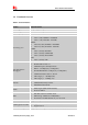
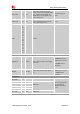
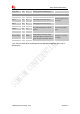
Keypad interface
KBR0 29 DOH
Bit 0 drive to the pad matrix
KBC0, KBC1, KBC2,
KBC3, KBR0 and
KBR2 pins can be
configured as SD2
interface. If unused,
please keep them
open.
KBR1 33 DOH Bit 1 drive to the pad matrix
KBR2 30 DOH Bit 2 drive to the pad matrix
KBR3 35 DOH Bit 3 drive to the pad matrix
KBR4 34 DOH Bit 4 drive to the pad matrix
KBC0 28 DI,PD
Bit 0 for sensing key press on pad
matrix
KBC1 27
DI,PD Bit 1 for sensing key press on pad
matrix
KBC2 31
DI,PD Bit 2 for sensing key press on pad
matrix
KBC3 32
DI,PD Bit 3 for sensing key press on pad
matrix
KBC4 36
DI,PD Bit 4 for sensing key press on pad
matrix
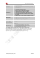
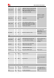
PCM interface
PCM_OUT 73 DO PCM data output.
If unused, please keep
them open.
PCM_IN 74 DI PCM data input.
PCM_SYNC 75 DO PCM data frame sync signal.
PCM_CLK 76 DO PCM data bit clock.
GPIO
NETLIGHT 51 DO
LED control
o
utput
as network
status indication.
If unused, keep them
open.
FLIGHTMODE
54 DI,PU
Flight Mode
control
i
nput
.
High level(or open): Normal Mode
Low level: Flight Mode
STATUS 49 DO
O
perating status
o
utput
.
High level: Power on and firmware
ready
Low level: Power off
GPIO41 52 IO GPIO
GPIO43 50 IO GPIO
SD1_DET 48 IO
Default: GPIO
Optional: SD card detecting input.
H: SD card is removed
L: SD card is inserted
USIM_DET 53 IO
Default: GPIO
Optional: USIM card detecting
input.
H: USIM is removed
L: USIM is inserted
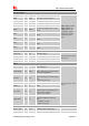
RF interface
MAIN _ANT 82 AIO MAIN antenna soldering pad
GNSS_ANT 79 AI GNSS antenna soldering pad