
Manual
1
Network VP Sensor Input Kit (SIK)
Installation Instructions
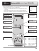
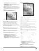
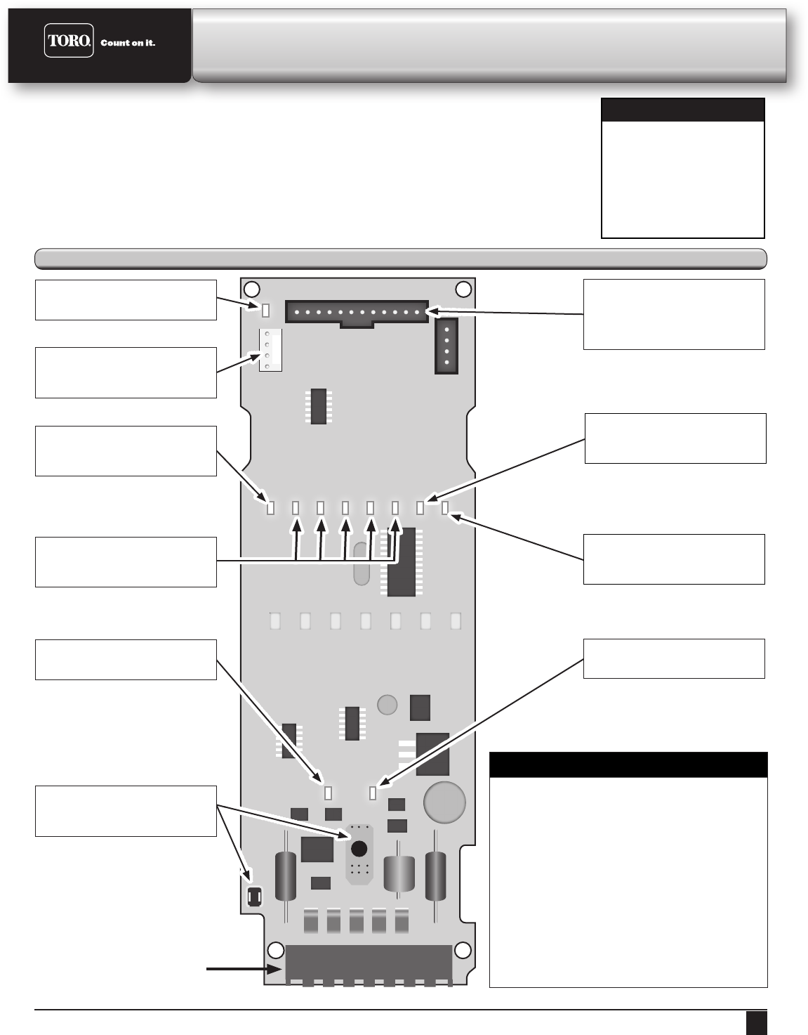
Sensor Input Board Overview
Temperature LED
Indicates if a temperature
sensor is present.
Transmit LED
Indicates data packet
is being sent.
IN1 LED - Pressure
Indicates if a pressure sensor
is present.
Temperature Probe Connector
Connector for temperature
sensor probe.
Power Distribution Connector
Receives 5V and 9V to
power the Sensor Input
Board.
5V LED
Indicates 5V is active.
24V LED
Indicates 24V is active.
12V LED
Indicates 12V is active.
24V Connections
Connection to receive 24V
AC from satellite.
IN2-IN6 LEDs
Indicate sensor activity for
channels IN2-IN6.
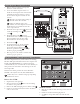
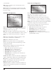
IN 1
IN 2
IN 3
IN 4
IN 5
IN 6
COM
12V
Terminals
Terminal Description
IN 1 Pressure Sensor Input
IN 2
Flow, Rain, or Status Sensor Input
IN 3
Flow, Rain, or Status Sensor Input
IN 4
Flow, Rain, or Status Sensor Input
IN 5
Flow, Rain, or Status Sensor Input
IN 6
Flow, Rain, or Status Sensor Input
COM
12 V Ground or Common
12V 12 V DC Output
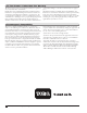
e Sensor Input Kit receives sensor data from status, ow, temperature, rain buckets, and
pressure sensors, then relays that data to the Lynx computer. ere, it can be used to monitor
conditions and automatically respond to user-dened alarms.
• Sensor data is stored in the VP satellite for 12 hours and transmitted back to Lynx
every 2 hours.
• Current sensor information and alarm status can be viewed in the VP faceplate.
• Central-based or stand-alone alarm responses can be congured for any sensor input.
Kit Components
• Sensor Input Board
• Surge Board
• Mounting hardware
• Fuse
• Cables