
Use and Care Manual

First Choice When Quality Matters
NORTH
AMERICA
Plunger Pumps
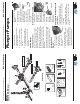
Operating Instructions and Parts Manual RSV Series Pumps
Oil Change
Change oil after fi rst 50 hours of use.
Then every 500 hours. Refer to parts
breakdown for oil type.
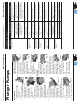
Servicing the Built-in Unloader
and Check Valve
These partw are serviced as assenbled
kits.
Tools required: 3/8” drive ratchet, 19mm
deepwell socket, medium strength
thread locker, needle nose pliers.
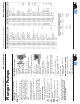
Check Valve Removal:
1. Remove the chemical
injector discharge
nipple. Use the needle
nose pliers to lift out
the check valve. (See
Figure 29)
Check Valve Assembly:
1. Place the check valve into the
discharge outlet with the pointed
side going in fi rst (NOTE: older
model pumps have
springs that go into
the hollow portion
of the valve, newer
models do not have
springs.) (See Figure
30)
2. Inspect the o-rings on the injection
nipple, if damaged
replace. Place small
amount of thread locker
on the thread and
tighten. (See Figure 31)
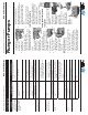
Unloader Removal:
Tools required: 3/8” rachet, 22mm deep
well socket, crescent wrench, small
hammer, 6mm x approximately 8mm or
longer, medium strength thread locker.
Unloader assembly removal:
1. Using the 22mm
socket rotate the
pressure adjusting
cap so both set of
hexes are alligned.
Use screw to remove
the complete unloader
assembly. (See Figure 32)
1. Screw the 6mm bolt into the
unloader piston seat, grab the bolt
with the crescent
wrench just under
the head. Using
the hammer tap
the bottom of the
wrench. The seat will pop
out. (See Figure 33)
Unloader assembly:
1. Piston seat installation
screw the new seat
onto the bolt (NOTE:
the fl at side is the
bottom). Push squarly
into the unloader base
and tap into place with
the hammer. (Remove
the bolt) (See Figures 34
& 35)
2. Place a small amount
of thread locker on
the unloader cartride
threads and screw into the
base and tighten.
OTE:
older
Figure 30
Figure 31
Figure 29
Figure 35
Figure 34
Figure 32
Figure 33
Service Pumps (continued)
Plunger Pumps
Operating Instructions and Parts Manual RSV Series Pumps
First Choice When Quality Matters
NORTH
AMERICA
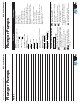
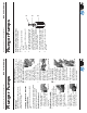
Unloader Adjusting Instructions
Follow these easy steps to adjust the
pressure:
1. Loosen nut (pos. #3) with 10mm
wrench.
2. Turn brass (pos. #4) clockwise until
it stops.
3. Start pump, watch pressure gauge
and turn (pos. #2) using 3mm hex
clockwise until recommended/rated
pressure is obtained. Line pressure
will be approximately 200 psi less
then actual head pressure. DO NOT
set line pressure to rated.
4. Release trigger and make sure there
is minimal spike (200-300 psi) (Re-
peat this step two or three times).
5. Tighten nut (pos. #3) down against
(pos. #4).
4
2
3
Service Pumps (continued)