
Use and Care Manual
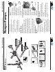

First Choice When Quality Matters
NORTH
AMERICA
Plunger Pumps
Operating Instructions and Parts Manual RSV Series Pumps
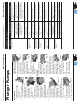
Symptom Possible Cause(s) Corrective Action
Oil leak between
crankcase and pump-
ing section
Worn rod oil seals Replace crankcase piston rod
seals
Frequent or prema-
ture failure of the
packing
1 Cracked, damaged or worn
plunger
1 Replace plungers
2 Overpressure to inlet
manifold
2 Reduce inlet pressure
3 Material in the fl uid being
pumped
3 Install proper fi ltration on pump
inlet plumbing
4 Excessive pressure and/or
temperature of fl uid being
pumped
4 Check pressures and fl uid inlet
temperature; be sure they are
within specifi ed range
5 Running pump dry 5 Do not run pump without water
Pump runs but pro-
duces no fl ow
Pump is not primed Flood suction then restart pump
Pump fails to prime Air is trapped inside pump Disconnect discharge hose from
pump. Flood suction hose,
restart pump and run pump until
all air has been evacuated
Pump looses prime,
chattering noise,
pressure fl uctuates
1 Air leak in suction hose or
inlet
1 Remove suction line and inspect
it for a loose liner or debris
lodged in hose. Avoid all unnec-
essary bends. Do not kink hose
2 Clogged suction strainer 2 Clean strainer
Low pressure at
nozzle
1 Unloader valve is by-pass-
ing
1 Make sure unloader is adjusted
property and by-pass seat is not
leaking
2 Incorrect or worn nozzle 2 Make sure nozzle is matched
to the fl ow and pressure of the
pump. If the nozzle is worn,
replace
3 Worn packing or valves 3 Replace packing or valves
Pressure gauge fl uc-
tuates
1 Valves worn or blocked by
foreign bodies
1 Clean or replace valves
2 Packing worn 2 Replace packing
Low pressure 1 Worn nozzle 1 Replace with nozzle of proper
size
2 Belt slippage 2 Tighten or replace with correct
belt
Troubleshooting
Plunger Pumps
Operating Instructions and Parts Manual RSV Series Pumps
First Choice When Quality Matters
NORTH
AMERICA
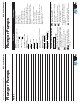
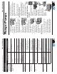
seal (Make sure it
is squarely seated).
(See Figure 21)
4. Installing the low-
pressure seal You
want the open side of the
seal to be pointed toward
the water side of the head (toward
the high-pressure seal) and the fl at
side toward the drive end of the
pump.
Place the seal into
the gland at an
angle, with your
fi nger push the
exposed side of the
seal towards the center
and work the seal into position.
After the seal is in the gland you
can work it into it proper position..
(See Figure 22)
5. Install the retainer
O-ring. (See Figure 23)
6. Squarely seat the
retainer into the head
and push with even
pressure until it snaps
into position. (See
Figure 24)
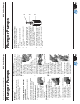
Inlet Valve Removal:
1. Remove the valve cap.
2. Inspect the valve cap O-ring for any
damage, replace if necessary.
3. Screw the machine screw into
the hole on top of the valve cage
(approx 1/8”). Using the diagonal
pliers grasp the screw at the lowest
reachable point. Using the pump
head as a base, push down on the
pliers, the valve will lift out.
4. Use a small probe to move the
poppet up and down to assure that
the valve is functioning properly
and that no debris is stuck in the
valve.
5. Inspect the valve o-ring for any
damage, replace if necessary.
Inlet Valve Assembly:
1. Insert the valve assembly squarely
into the port pushing it into place
with a deap well socket (you will
feel the valve assembly seat).
3. Install the valve cap and torque to
the proper specifi cation.
Pump Head to Drive End
Installation
1. Turn the crankshaft to align
the plungers as shown. (See
Figure 25)
2. Place the head
evenly onto the
plungers and push
it until it makes
contact with the
drive end of the
pump. (See Figure 26)
3. Torque the head
bolt as shown in the
tightening sequence
diagram.
(See Figure
27 & 28)
Figure 21
e
e
e
e
e
e
e
p
p
p
p
p
p
p
p
p
p
p
p
p
p
p
p
p
p
p
o
o
o
o
o
os
os
s
s
t
t
t
t
o
o
o
o
o
o
o
Figure 23
Figure 24
Service Pumps (continued)
Figure 22
Figure 25
Figure 26
Figure 27
Fig
Figure 28