
Use and Care Manual

First Choice When Quality Matters
NORTH
AMERICA
Plunger Pumps
Operating Instructions and Parts Manual RSV Series Pumps
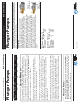
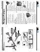
Disassembly:
1. First remove the eight
5mm head bolts. (See
Figure 10)
2. Place the screwdrivers
as shown between the
head and crankcase of the
pump, lifting one up
and the other down.
The head should
start to lift off of
the plungers. (See
Figure 11)
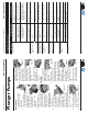
3. When you remove
the head you may notice
that some of the water
seals have stayed on the
plungers and some in
the head. To remove
the seals from the
plungers simple turn the
assemblies and pull off.
(See Figure 12)
4. If the seal assemblies
are in the head use
the channel lock
pliers to grab the
seal retainer on the
outside ring, twist
the retainer in either
direction (this is done to
free the retainer O-ring
which is stuck to the manifold) and
lift out. (See Figure
13)
5. With your fi nger pull
out the white restop
ring. (See Figure 14)
6. With your fi nger pull the
high-pressure seal and
head ring out of the
head. (See Figure 15)
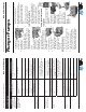
7. The low-pressure seal
is located in the brass
seal retainer. Using
the mechanics pick, go
in between the seal and
retainer and pull the
seal toward the center
and pull outwards. (See
Figure 16)
8. Remove the seal retainer
O-ring with the
mechanics pick. (See
Figure 17)
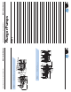
Assembly:
1. Install the plastic head
ring into the head
(the fl at side is on
the bottom). (See
Figure 18)
2. Install the high-
pressure seal. Place the
seal so the open “V” portion is
toward the head ring. You need
to place the seal at an angle and
pull and push to work the seal into
position with your
fi ngers (do not use any
tools you may damage
the seal). Make sure
the seal is totally
seated against the head
ring. (See Figure 19 &
20)
3. Place the white restop
ring so it mates to the
top of the high pressure
Figure 11
Figure 12
Figure 14
s
s
s
s
s
s
s
s
s
s
s
s
s
s
s
s
s
s
s
s
s
s
s
s
s
s
r
Figure 13
Figure 10
Figure 16
Figure 17
Figure 15
Figure 18
Figure 20
y
y
y
y
y
y
y
y
y
y
y
y
y
y
y
y
y
y
y
y
y
y
y
y
y
y
y
y
y
y
y
y
y
y
y
Figure 19
Service Pumps (continued)
Plunger Pumps
Operating Instructions and Parts Manual RSV Series Pumps
First Choice When Quality Matters
NORTH
AMERICA
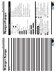
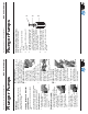
Symptom Possible Cause(s) Corrective Action
Low pressure (cont.) 3 Air leak in inlet plumbing 3 Disassemble, reseal and reas-
semble
4 Relief valve stuck, partially
plugged or improperly
adjusted valve seat worn
4 Clean and adjust relief valve;
check for worn or dirty valve
seats
5 Worn packing. Abrasive
in pumped in cavitation.
Inadequate water
5 Install proper fi lter suction at
inlet manifold must be limited to
lifting less than 20 feet of water
or 8.5 psi vacuum
6 Worn inlet, discharge valve
blocked or dirty
6 Replace inlet and discharge valve
Pump runs extremely
rough, pressure very
low
1 Inlet restrictions and/or air
leaks.
1 Clean out foreign material
2 Stuck inlet or discharge
valve
2 Replace worn valves
Water leakage from
under manifold
Worn packing or cracked
plunger
Install new packing or plunger
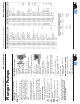
Slight leak, oil leak-
ing in the area of
crankshaft
1 Worn crankshaft seal or
improperly installed oil seal
o-ring
1 Remove oil seal retainer and
replace damaged 0-ring and/or
seals
2 Bad bearing 2 Replace bearing
Excessive play in the
end of the crankshaft
pulley
Worn main bearing from
excessive tension on drive
belt
Replace crankcase bearing and/or
tension drive belt
Water in crankcase 1 Humid air condensing into
water inside the crankcase
1 Change oil intervals
2 Worn packing and/or
cracked plunger
2 Replace packing. Replace
plunger
Loud knocking noise
in pump
1 Cavitation or sucking air 1 Check water supply is turned on
2 Pulley loose on crankshaft 2 Check key and tighten set screw
3 Broken or worn bearing 3 Replace bearing
Troubleshooting (cont.)