
Use and Care Manual

First Choice When Quality Matters
NORTH
AMERICA
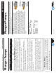
Plunger Pumps
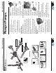
Operating Instructions and Parts Manual RSV Series Pumps
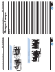
RSV
3400 RPM
Repair Kits
69
58
59
64 70 66
67
28
12
21
20
22
24
25
26
27
29
33
32
31
17
30
34
11
35
36
37
38
39
40
41
42
43
44
45
46
47
48
49 50
53
52
51
54
55 56
35
33
23
19
18
17
16
15
14
13
12
11
10
9
8
7
6
4
5
4
3
2
1
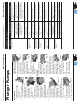
"D" VERSION Ø 3/4”
TYPE F25
68
58
59
64 71 66
67
"D" VERSION Ø 1”
TYPE F40
62
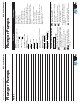
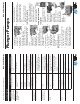
Valves
Kit 2186
35(6)
Unloader
Kit 2280
15
14
13
12
11
10
9
8
7
6
5
4(2)
3
2
1
Support Ring
Kit 2191
36(3)
O-Rings
Kit 2190
7
(1)
8(1)
9(1)
11(4)
19(1)
21(1)
22(1)
26(1)
12(2)
15(1)
17(2)
18(1)
46
Oil Seals
Kit 2188
64
54
44(3)
Water Seals
Kit 2189
38
(3)
40(3)
42(3)
37(3)
41(3)
Pistons
Kit 2187
51
(3)
Plunger Pumps
Operating Instructions and Parts Manual RSV Series Pumps
First Choice When Quality Matters
NORTH
AMERICA
through the pump.
3. Flush the pump with fresh water
before the next use.
4. In freezing conditions failure to
do this may cause internal pump
damage.
5. For long periods of storage in
non-freezing areas the solution
will keep the seals and O-rings
lubricated.
Service Pumps
Servicing the Valves
The inlet and discharge valves in this
series pumps are all the same. The
valves are located under the six 19mm
hex plugs. The inlet valves are located
on the inside portion of the head under
the seal assemblies and the discharge
valves are located on the top row of the
pump head.
Tools required: #8-32x” machine screw
and diagonal pliers, screw driver, 19mm
socket, ratchet, and torque wrench.
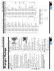
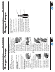
Discharge Valve
Removal:
1. Remove the valve
cap. (See Figure 5)
2. Inspect the valve
cap O-ring for any
damage, replace if
necessary.
3. Screw the machine screw
into the hole on top of the valve
cage (approx 1/8”). Using the
diagonal pliers grasp the screw at
the lowest reachable point. Using
the pump head as a base, push
down on the pliers, the
valve will lift out. (See
Figure 6)
4. Use a small probe to
move the poppet up
and down to assure that
the valve is functioning
properly and that no
debris is stuck in the
valve. (See Figure 7)
5. Inspect the valve o-ring
for any damage, replace
if necessary.
Discharge Valve Assembly:
1. Insert the valve
assembly squarely
into the port
pushing it into place
with a deap well
socket (you will feel
the valve assembly
seat). (See Figure 8)
3. Install the
valve cap
and torque
to the proper
specifi cation.
(See Figure 9)
Servicing the Packings/Seals and
Inlet Valves
To access the water seals and inlet
valves for inspection or replacement,
you will fi rst need to remove the head
of the pump.
Tools required: 5mm hex socket,
ratchet, (2) long screwdrivers, channel
lock pliers, mechanics pick and torque
wrench.
Figure 5
Figure 6
Installation (continued)
Figure 7
Figure 9
Figure 8