
Instructions / Assembly
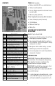
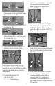


6. The following steps will cover the assembly of
the opposite side to the water and sand tables
(Fig. 6A - 6C).
(1) J Main Water Feed (Top)
(1) K Main Water Feed (Bottom)
(2) N 33.5" Pipe (Latteral Supports)
(1) W Elbow (Yellow)
(1) P 24" Pipe (Front Upright - Top)
(1) U 24" Pipe With Coupling (Front
Upright - Bottom)
Connect by tightening the union.
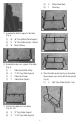
7. Connect the two halves of the waterpark
together by attached the Cross Feed Line and
install the lateral support for the bucket
assembly (Fig. 7A - 7C).
(1) L Cross Feed Line
(1) N 33.5" Pipe (Lateral Supports)
Connect by tightening the union.
Stand the structure and align the union with
the water and sand table structure. Tighten the
union to connect the two structures
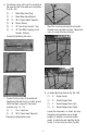
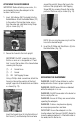
8. Assemble the Dump Bucket (Fig. 8A - 8D).
(1) B Dump Bucket
(1) D Bucket Support Rod
(1) F Bucket Support Arm (Left)
(1) G Bucket Support Arm (Right)
Layout the components as shown, ensuring
the yellow and red elbows are arranged
properly. In addition, ensure the counter
weight, inside the bucket (identified by the
arrow), is in the correct position (Fig. 8A).
4
Fig. 6A
Fig. 6B
Fig. 6C
Fig. 7A
Fig. 7B
Fig. 7C