
Installation Guide

59
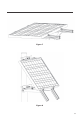
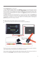
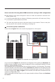
Figure 7.1
Completed 24V off-grid system
Please refer to
Figure 7.1
for the overall wiring diagram for a 24V system.
7.2 Overall system connections
As you can see from
Figure 7.1
, the batteries are configured in 24V by placing two
identical
12V
batteries in series. Likewise, the solar array is configured in 24V by connecting two identical 12V solar
panels (e.g. RNG-100D-SS) in series.
The connections for a 24V off-grid system are very similar to those of a 12V connection. The process
should be followed in the same way as outlined in
Sections 6.1 to 6.4
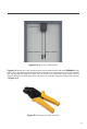
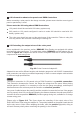
. The only difference is that
the fuse selection changes, since a series connection increases the system Voc to ~45v. Therefore a
fuse with a voltage rating of
50v or higher
is recommended, since Maxi and ATO blade fuses have
a maximum voltage rating of 32v.
With this being said, the same steps for a 12V system should be followed. Please read
Sections
6.1 to 6.4.
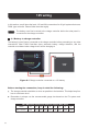
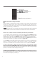
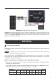
Please note the following about PWM controllers running in 24V configuration:
24V panels or 12V panels configured in series to make 24V should be used with 24V
battery system only.
It is not recommended that you charge a 12V battery system with a 24V solar array. Doing
so will result in a performance loss of 50%.
The solar array should not max out the rated power of the controller. Failure to obey this
rule may result in the controller overheating or catching fire.