
Installation Guide


CAUTION
CAUTION
WARNING
Connect battery terminal wires to the charge controller FIRST then
connect the solar panel(s) to the charge controller. NEVER connect
solar panel to charge controller before the battery.
Do not over-torque or over tighten the screw terminals. This could
potentially break the piece that holds the wire to the charge controller.
Refer to the technical specifications for max wire sizes on the controller
and for the maximum amperage going through wires.
The front of the Adventurer will serve as a heat sink, therefore it is important to ensure that the
mounting location is not near any heat generating sources and ensure that there is proper
airflow across the faceplate of the Adventurer to remove the heat dissipated from the surface.
WARNING
Never install the controller in a sealed enclosure with flooded batteries. Gas can
accumulate and there is a risk of explosion.
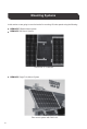
Mounting Recommendations:
The Adventurer is designed for flush mounting on a wall. It consists of a face plate with
projecting terminals on the backside for connecting the battery bank, panels, and optional
sensors for accurate battery voltage sensing and battery temperature compensation. If utilizing
the wall mount, then the wall will be required to be cut to accommodate the projecting terminals
on the backside. Make sure that the pocket of the wall cut leaves enough space to not damage
the terminals when the Adventurer is being pushed back into the cut out section of the wall.
NOTE
The Adventurer comes equipped with screws for wall mounting. If they are not
suitable try
using Pan Head Phillips Screw 18-8 Stainless Steel M3.9
Size 25mm length screws.
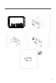
1)
Choose Mounting Location—
place the controller on a vertical surface protected from
direct sunlight, high temperatures, and water. Make sure there is good ventilation.
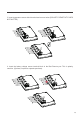
3)
Cut out Wall section—
the recommended wall size to be cut should follow the inner
protruding part of the charge controller while being careful not to go past the mounting holes.
The depth should be at least 1.7 inches (43mm).
2)
Check for Clearance—
verify that there is sufficient room to run wires, as well as
clearance above and below the controller for ventilation. The clearance should be at least 6
inches (152mm).
4)
Mark Holes
6)
Secure the charge controller.
5)
Drill Holes
05