
Installation Guide

58
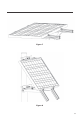
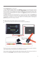
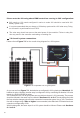
Figure 6.4
shows the complete wiring of a typical off-grid system. It includes fuses for safety
and protection. This configuration shows only one panel and one battery connected to the
controller. In
Sections 8 and 9
, more panel and battery configurations (respectively) will be
described. Instructions will follow.
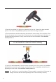
The batteries must first be wired to the charge controller before the solar panel is
connected to the charge controller.
As we mentioned in last
Section
, the battery bank must first be connected to the charge
controller before any other connections are made. This will allow the controller to set the 24V
charging parameters automatically.
CAUTION
In this section we will show the basic connections for a 24V battery system. Please follow them
thoroughly.
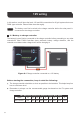
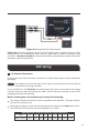
7.1 General information
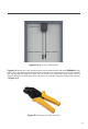
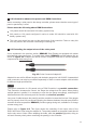
Female connector
24V wiring
Before starting the connections keep in mind the following:
The charge controller should be as close as possible to the batteries. This helps keeping
line loss to a minimum level.
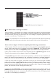
Remember to always use the recommended gauge size based on the
total
input current.
The PWM 30A LCD controller can handle gauges up to 6 AWG.
Figure 6.4
Completed 12V off-grid system
Male connector
AWG 16 14 12 10 8 6 4 2 0
Max. Current
55A40A30A25A18A 75A 95A 130A
170A
NEC Maximum Current for different Copper Wire Sizes