RENOGY Off-Grid Kit RENOGY Off-grid kit general Manual Version 1.
Table of Contents General Information 04 Charge Controller Installation 05 Mounting Recommendations 05 Wiring 07 Mounting Systems 01 10 Z-Bracket Mounting 11 Making Brackets to panel Frame 13 Install of Panel to General Mounting Surface 18 Install of Panel to RV Roofs 23 Rail Mount System 30 Roof Securements for Attachment Points 33 Rail System Construction 36 Rail Seating 39 Panel Securement .
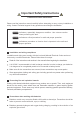
Important Safety Instructions Please save these instructions. Please read the instruction manual carefully before attempting to carry out any installation or wiring. Contact Technical support for any questions concerning the installation. WARNING CAUTION NOTE Indicates a potentially dangerous condition. Use extreme caution when performing this task. Indicates a critical procedure for safe and proper operation. Indicates a procedure or function that is important to the safe and proper operation.
Care should be taken to ventilate the battery area and follow the battery manufacturer’s recommendations. Never smoke or allow a spark or flame near the batteries. Use caution to reduce the risk of dropping a metal tool on the battery. It could spark or short circuit the battery or other electrical parts and could cause an explosion. Remove metal items such as rings, bracelets, and watches when working with batteries.
General Information A new RENOGY Off-Grid Solar Kit will provide you with a clean, silent, and sustainable way of ensuring that batteries are fully charged and capable of providing a continuous supply of electricity. Each kit comes equipped with a high quality solar panel that features highly efficient silicon solar cells. If you have purchased a RENOGY Off-Grid Solar Kit, Renogy Solar Charge Controller is also included in the package.
WARNING CAUTION CAUTION Connect battery terminal wires to the charge controller FIRST then connect the solar panel(s) to the charge controller. NEVER connect solar panel to charge controller before the battery. Do not over-torque or over tighten the screw terminals. This could potentially break the piece that holds the wire to the charge controller. Refer to the technical specifications for max wire sizes on the controller and for the maximum amperage going through wires.
06
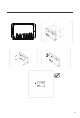
1. Unscrew battery terminals and connect battery connections 2.
3. Insert temperature sensor block terminal and connect wires (POLARITY SENSITIVITY DOES NOT MATTER) 4. Insert the battery voltage sensor terminal block in the Batt Remote port. This is polarity sensitive. (Optional, requires a separate purchase).
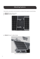
Mounting Systems In this section we are going to cover the basics for mounting 12V solar panels using the following: RENOGY Z-Bracket Mount system RENOGY Rail Mount System Rail mount vs.
Z-Bracket Mounting RNG-MTS-ZB RENOGY Z-Bracket Mounting The Renogy Z-Bracket Mount System is designed to support the installation of single panel units, generally in off-grid installations. These units are ideal for installation on RV roofs and non-inhabited dwellings such as sheds or garages. It is also suited as attachment to a user made structure such as a wooden frame. The system comes complete with all fasteners to secure the system to the installation surface.
Recommended tools to have before installation: The following tools and equipment are highly recommended to have available to assist with installation but are in no way a comprehensive list of tools that can ease installation. Installers feel free to substitute comparable equipment where appropriate. Image 11 Composant Description Ratchet Wrench Allows for tightening of fasteners. 6mm Socket Drive Used with ratchet to tighten down bolted joint between panel and Z-Bracket.
Tape Measure Ratchet Wrench WARNING May be useful in planning Z-Bracket configuration and positioning. Caulking Gun Used to direct sealant into penetrations to avoid leaking. Compatible Sealant Sealant compatible with your specific installation. Spirit Level Used to ensure panel is level and/or plumb to the mounting surface and orientation. Installation on shingle roofs is not recommended. System is not designed with these roof types in mind.
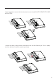
Making Brackets to panel Frame RG01 IP65 1000V 2mm2 NOTE Various solar modules will have different varieties of mounting hole locations. Please align brackets in a way that will evenly support the module.
RG01 IP65 1000V 2mm2 RG01 IP65 1000V 2mm2 14
Repeat for each Z-Bracket in the set at each corner.
Install of Panel to General Mounting Surface NOTE Ensure screw locations are backed by structural element such as a rafter, stud, etc.
17
NOTE Orient panel in level/plumb layout as desired before fixing in position.
NOTE Begin new fastener at indicated location first to secure panel in level plumb/level layout. Repeat for all fastener locations.
NOTE Seal around all edges of bracket and screws. Repeat for all brackets.
Install of Panel to RV Roofs Installation on to the roofs of RV’s typically requires more specialized instruction due to the nature of construction of most commercially available RV roofs. Please note that this section includes the use of a fastener type NOT included in the Z-Bracket kit. This section is included for convenience of customers installing to an RV roof. The instructions listed in this section are a modification of the normal installation, all other steps are to be completed normally.
NOTE Mark all holes locations in this step as the panel must be removed for well nut insertion.
23
NOTE Use of sealant is optional with a well nut but sealing will add extra assurance. Seal under well nut head.
Repeat for all holes. NOTE Orient panel in level/plumb layout as desired before fixing in position.
NOTE Screw has compressed and expanded the well nut, binding into the roof material. Repeat for all fasteners.
Recommended tools to have before installation: The following tools and equipment are highly recommended to have available to assist with installation but are in no way a comprehensive list of tools that can ease installation. Installers feel free to substitute comparable equipment where appropriate. Image Composant Wrench 27 Description Allows for tightening of fasteners 6mm Hex Bit w/ Socket Drive Bit to be used with torque wrench to drive hex cap bolts within the system assembly.
Compatible Sealant Sealant compatible with your specific roof installation. Consult with documentation/warranty paperwork for the roof. 7/32” Drill Bit Used to drill pilot holes for the roof attachment bolts. Recommended 3” in length. 5/16” Lag Bolt Fastener to be torqued down into roof studs. Secures L-Feet to roof. Recommended 3” in length. Needs compatible zinc-coated washer. ½” Socket Drive Used in conjunction with the torque wrench to tighten down lag bolts into the roof structure.
Roof Securements for Attachment Points CAUTION NOTE 29 If using an alternative base for the L-Foot such as the MTS-QMSC or a third party stand-off system to clear obstructions, please consult those product manuals for additional instruction before proceeding with this section. Leave L-Foot fasteners attached to the unit as they come packaged. This will ease attachment to the railing components later in the installation.
NOTE • Rafters usually spaced 16” or 24” increments. Installer should verify. • Ensure attachment points (L-Feet) are spaced at maximum, 48” apart. •Rails should be spaced apart a maximum of 60% the length of the spanning panel edge.
NOTE Start lag bolt threading by hand.
Rail System Construction 1 2 32
3 4 33
5 6 34
7 Repeat for all continuous rail sets.
2 3 36
4 5 37
7 Panel Securement 1 WARNING End clamps must be installed a minimum of 1” (30 mm) from the rail edges.
2 3 39
NOTE Ensure that the End Clamp is spaced a minimum distance of 1.25” from rail end face.
6 7 Continue mid-clamp procedure for each additional panel.
NOTE Ensure that the End Clamp is spaced a minimum distance of 1.25” from rail end face. 8 WARNING End clamps must be installed a minimum of 1” (30 mm) from the rail edges. 9 Repeat procedure for each panel row.
RENOGY Pole Mount System The Renogy Pole Mount System is designed for off-grid applications, when mounting to a roof is not ideal. It will support off-grid systems, and panels up to 100W. The system comes complete with all fasteners to secure the system to the installation surface. This system makes the installation of small solar systems easy, affordable and quick.
Fasten L-Channels to L-Brackets A. Place Washer (H) flush to top surface of L-Channel (B), and align the holes. B. Slide the Spring Washers (I)) onto the Cap Head Bolt’s (G) thread so that the bottom face of the Cap Head Bolt is touching the top surface of the spring washer. C. Feed the thread of the Cap Head Bolt (G) through both L-Channel (C) and Washer’s hole. Repeat for all 4 holes. D.
Slide U-Bolt through back face of L-Channel A. Hold the assembled system up to pole so that L-Channel (B) back face is flush to surface of the pole and slide the U-Bolt (E) through the holes. B. Fasten U-Bolt (E) with a large washer (L) and 1 or 2 nuts (M) (depending on how much thread is available. C. Repeat for bottom L-Channel and last U-Bolt.
Attach Support Arm to bottom L-Brackets A. Flush Support Arm (D) to L-Bracket (C) and align the holes. B. Place washer on Support Arm (D) surface and align holes. C. Feed a Cap Head Bolt (G) through Support Arm (D), and the L-Bracket (C). D. Fasten it with small Nuts (K). D. The orientation should be close to Figure 3. E. Repeat for the other side.
Fasten T-Slotted Brackets to top L-Channel using the L-Brackets A. Slide T-Bolt (F) through the top of the T-Slotted Bracket (A) approximately 35mm (1.4in) down. There is no need to place a spring washer, or regular washer through the T-bolt. B. Feed thread of the T-Bolt (F) through L-Bracket (C) and angle T-Slotted Bracket (A) as desired. The optimum angle will vary with your apparent position, relative to the sun. Range is usually from 60-75 degrees from the vertical. C.
Fasten the bottom of the T-Slotted Brackets to Support Arm A. Slide T-Bolt (F) through same slot as previous step. The distance that the bolt should slide depends on the angle that the T-Slotted Bracket (A) was fastened to the top L-Channel (B). Usually anywhere from 150mm to 250mm (6in to 9.8in) although it can exceed that if necessary. B. The back planes of both L-Channels (B) should be parallel and flush to the pole. Achieving this may require reorienting the T-Slotted Bracket (A).
Slide panel onto brackets and fasten with end lamps A. Hold the panel up to the pole mount to determine approximate position that End Clamps (J) must be to hold panel. B. Start with the bottom clamps since they will hold most of the load. C. Slide a T-Bolt (F) through T-Slotted Bracket (A) to the appropriate location. D. Orient the clamps as they are in Figure 6. E.
Figure 7 Figure 8 50
Solar Connectors The Positive (+) and Negative (-) outputs of a solar panel are fed through a watertight junction box. The appropriate wire length is wired to the junction box for further connections. The solar panels supplied in each kit are provided with approximately 3 ft. each of both Positive and Negative wires that are pre-connected to the junction box. The free ends of the wires are terminated with a special type of mating solar connector..
Junction box Female connector − Male connector + Figure 5.2 Back view of RNG-100D Figure 5.2 shows the solar connectors that come preassembled with each RENOGY solar panel. When purchasing unassembled solar connectors for custom cabling, it is recommended that the appropriate crimper is used; this will avoid loose connections and create a strong internal contact when mating the solar connectors. An example of a great crimping tool is shown in Figure 5.3. Figure 5.
12V wiring In this section, we will show the basic 12V and 24V connections for off-grid systems that use a PWM- type controller. Please follow them thoroughly. CAUTION The battery must first be wired to the charge controller before the solar panel is connected to the charge controller. 6.1 Battery to charge controller The battery(s) must first be connected to the charge controller before proceeding to any other connections.
Refer to Figure 6.1 for connections. 1. First, connect the negative cable to the negative (−) battery post. The best way to secure the battery cable to the battery post is by using a ring terminal. A bolt is sufficient to secure the ring terminal onto the battery post; doing so will allow for great electrical contact. Next, connect the bare stranded portion of the cable to the negative (−) battery input terminal on the charge controller. 2.
3. Once the fuse holder is in place, don’t attach a fuse just yet. Connect the bare stranded portion of the cable to the positive (+) battery terminal on the charge controller. 4. The fuse between controller and battery should be the current rating of the controller. Once the fuse is properly sized, ensure that all connections were made properly, and that there are no loose connections present. Finally, insert the fuse into the fuse holder. The controller should power on.
6.2 Information about solar panels and PWM Controllers When connecting a solar panel to the charge controller, please ensure that the correct type of panel or panel array is used. Please note the following about PWM Controllers: 12V panels should be used with 12V battery systems only 24V panels or 12V panels configured in series to make 24V should be used with 24V battery systems only The solar array should not max out the rated power of the controller.
Male connector To Charge Controller Female connector Fig. 6.3 Solar panel and adapter kit 6.4 Solar Panel to charge controller Once the battery is connected to the charge controller and the panel(s) are positioned and mounted in the desired location, we are ready to connect the panel(s) to the charge controller. Panels should be mounted in a place that is free from shading by neighboring obstacles such as vents, air-conditioners, TV antennas, etc.
Male connector Female connector Figure 6.4 Completed 12V off-grid system Figure 6.4 shows the complete wiring of a typical off-grid system. It includes fuses for safety and protection. This configuration shows only one panel and one battery connected to the controller. In Sections 8 and 9, more panel and battery configurations (respectively) will be described. Instructions will follow. 24V wiring 7.1 General information In this section we will show the basic connections for a 24V battery system.
Please note the following about PWM controllers running in 24V configuration: 24V panels or 12V panels configured in series to make 24V should be used with 24V battery system only. It is not recommended that you charge a 12V battery system with a 24V solar array. Doing so will result in a performance loss of 50%. The solar array should not max out the rated power of the controller. Failure to obey this rule may result in the controller overheating or catching fire. 7.
Multiple panels/strings in parallel A parallel connection is achieved by joining all of the positive (+) and negative (-) nodes together. When placing panels in parallel, it is recommended that the voltage levels are within specification. In other words, the Vmp (maximum power voltage) of the panels must all be within 10% of each other. Typically, connecting panels in parallel is achieved through using identical panels.
8.2 Three adjacent panels in parallel (12V systems) To Charge Controller Figure 8.3 Three RNG-100D Panels in parallel Three solar panels is the maximum amount of panels that can be connected in parallel if they are adjacent to one another, without using extra cabling. Fig. 8.3 above shows the arrangement for connecting three solar panels in parallel. Remember that this arrangement is applicable if the three solar panels are to be mounted adjacent to one another.
Fig. 8.4 shows the arrangement for connecting four solar panels in parallel. This arrangement is applicable if the solar panels are to be mounted in a 2x2 configuration as shown above. Please note that the positioning of the junction boxes must be followed for the cables to reach the Solar Y Branch Connectors. This connection requires three (3) pairs of Solar Y Branch Connectors.
8.4 Four panels in series-parallel (24V systems, 2x2 configuration) Junction box this way up To Charge Controller To Charge Controller Junction box this way up Figure 8.6 Four RNG-100D Panels in series-parallel configuration For 24V systems, Fig. 8.6. Shows two strings of panels in parallel. Each string consists of two panels in series. No additional cabling is required if the solar panels are to be mounted in a 2x2 configuration as shown above. Please note the orientation of the junction boxes.
Battery Configurations The battery system can also be configured to create a “bank” of batteries. In this section, we cover the most basic configurations. When wiring batteries, extreme attention should be given. Never short a battery, as high currents can cause severe burns or even death. HAZARDS It is recommended that insulated/non-conducting tools be used when working with batteries. Never leave tools on top of the battery. Always wear eye protection.
9.2 Parallel connection of batteries (12V) Figure 9.2 Two 12V batteries connected in parallel When two or more batteries are connected in parallel, their voltage remains the same but the Amp-hour ratings add up. Fig. 9.2 shows two 12V batteries in parallel forming a “bank”. For example, say each battery has 100 Ah. When connected in parallel they will form a battery bank of 12V with a capacity of 200 Ah.
9.3 Series – Parallel connection of batteries (12V) Figure 9.3 Four 6V batteries connected in series – parallel Fig. 9.3 shows two strings in parallel; each string consists of two 6V batteries in series. For example, say each battery has 225 Ah. Each string would have a voltage of 12V with a capacity of 225 Ah. When these strings are paralleled, the total capacity of the battery bank will be 12V at 450Ah.
9.4 Series connection of batteries (24V) Figure 9.4 Two 12V batteries connected in series Wiring two 12V batteries in series as shown in Fig 9.4 will result in a 24V system. The same idea applies if you place four 6V batteries in series (Fig 9.5). Remember that when batteries are in series, the voltages add, but the total capacity of a string of batteries stays the same. For example, if two 12V batteries with 150Ah rating are wired in series, the resulting system would be 24V at 150Ah.
9.5 Series-Parallel connection of batteries (24V) Figure 9.6 Four 12V batteries connected in series – parallel Multiple strings of batteries can be wired in parallel to increase the capacity. Figure 9.6 shows a battery bank with two strings of batteries. Each string consists of two 12V batteries in series. For example, if wiring four 12V/150Ah batteries like as shown in Figure 9.6, then each string will have a total capacity of 24V/150Ah.
Inverter Wiring 10.1 General information about power inverters A power inverter, or inverter, is an electrical device that changes direct current (DC) to alternating current (AC); the converted AC can be at any required voltage and frequency with the use of appropriate transformers, switching, and control circuits. DC In AC Out Figure 10.1 Simple diagram on how the inverter works WARNING Please read these instructions carefully before attempting to carry out any installation and wiring.
Please refer to Fig. 3. Each end of the battery tray cables should have a “ring terminal” type of connector. These connectors make it easy to achieve a secure and strong connection. Once the cables are connected and bolted down to the inverter, connect the black cable to the negative post of the battery (-). Then, connect the red cable to the positive post of the battery (+).
RENOGY.COM Renogy reserves the right to change the contents of this manual without notice. US 2775 E Philadelphia St, Ontario, CA 91761, USA 909-287-7111 www.renogy.com support@renogy.com CN 苏州高新区科技城培源路1号5号楼-4 JP https://www.renogy.jp supportjp@renogy.com CA https://ca.renogy.com supportca@renogy.com AU https://au.renogy.com supportau@renogy.com UK https://uk.renogy.com supportuk@renogy.com DE https://de.renogy.com supportde@renogy.com 400-6636-695 https://www.renogy.cn support@renogy.