
Use and Care Manual


Plunger Pumps
Operating Instructions and Parts Manual RMV Series Pumps
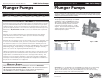
many factors. Water seals should be
replaced when water leak or a loss
of performance is noticed. Prompt
replacement of worn seals will insure
peak operating performance and
trouble free operation. The water
seals and their respective components
sometimes referred to as the packing
stack, will vary slightly between
models. But the constant between
models is that the packing stack will
consist of the following items:
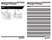
Piston Guides - which usually house
the low-pressure seal
Low-Pressure Seals
Piston Guide O-rings
High-Pressure Seals
Support Rings
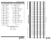
Torque Ratings Inch Pounds
(ft.lbs.)
Head 221 (19)
Valve Cap 221 (19)
Oil - AR64545 - Container is 4.5 fl uid
ounces. Specially formulated for the
demands of the RMV pump. See parts
breakdown. Do NOT change oil. Use
oil only to add if low.
NOTE: No other oil is factory approved
for this pump. Using any other oil
may result in Drive End Damage.
Winter or Long Time Storage
1. Drain all of the water out of the
pump.
2. Run a 50% solution of a RV or
non-toxic/biodegradable antifreeze
through the pump.
3. Flush the pump with fresh water
before the next use.
4. In freezing conditions failure to
do this may cause internal pump
damage.
5. For long periods of storage in non-
freezing areas the solution will keep
the seals and O-rings lubricated.
Plunger Pumps
Operating Instructions and Parts Manual RMV Series Pumps
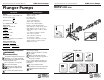
Figure 6
Figure 7
Figure 8
Figure 9
Figure 12
Figure 11
Figure 10
Figure 13
Figure 14
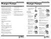
6. Inspect for any debris or damage.
7. Remove the valve O-ring.
Assembly:
1. Install the valve seat
O-ring squarely into
the bottom of the
manifold.
(See fi gure 11)
2. Insert the valve
assembly and push
squarely into the
O-ring. (See fi gure 12)
3. Install the high-pressure
packing by placing it into
the cylinder at an angle and then
pushing into place.
NOTE: The point of the “V” or
fl at side of the packing is pointed
at you.
4. Lubricate the packing retainer
O-ring with a light fi lm of oil and
install it into the cylinder.
5. Push it completely into
place.(See fi gure 13)
NOTE: The O-ring
will seat just inside the
manifold and you will hear a
slight pop.
6. Insert the low
pressure seal by
placing it into the
cylinder in at an
angle and pushing it into
place. (See fi gure 14)
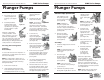
Service Pumps (Continued)
3. Install the valve cap and
torque to the proper
specifi cations. (See
fi gure 6)
Inlet Valves:
Disassembly:
1. Remove the manifold.
2. Remove low
pressure seals, insert
screwdriver under
seal lip and lift up.
(See fi gure 7)
3. Using a reversible
pliers, carefully remove
the packing retainers
(plunger guides). (See
fi gure 8)
NOTE: You do not want
to damage these so they can be
reused if not worn.
4. Remove the high-
pressure packing by
pulling straight out
with your fi nger. (See
fi gure 9)
5. Pull out the valve
cage/head ring
assembly, valve
poppet, spring and
O-ring.
(See fi gure 10)