
Use and Care Manual

First Choice When Quality Matters
NORTH
AMERICA
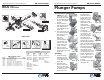
Plunger Pumps
Operating Instructions and Parts Manual RK Series Pumps
44
21
22
23
25
24
26
29
30
15
16
45
48
46
1
5
6
4
3
1
2
4
11
12
13
14
49
47
42
50
19 20
18
40
17
27
28
43
69
2
3
75
42
36
35
34
42
43
39
41
38
37
77
17
19
"N" VERSION
86
87 88 89
61
60
59
1763
62
64
65
"E" VERSION
TYPE F17
78
RKA
1750 RPM
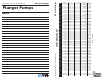
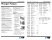
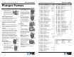
Repair Kits
Code Description Qty.
Special Parts / Kits
Legend
2809 Viton water seals Ø18 1
2810 Viton water seals Ø20 1
2811 Viton water seals Ø22 1
2819 Kit for up to 180° F Ø18 High Temp 1
2820 Kit for up to 180° F Ø20 High Temp 1
1837 Rail Kit 5/8” - 2 Rails & 4 Bolts (N only) 1
2633 Rail Kit 1-3/4” - 2 Rails & 4 Bolts (N only) 1
2633H Rail Kit 2-5/8” - 2 Rails & 4 Bolts (N only) 1
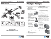
Valves
Kit 2864
3(6)
4(6)
Support Rings
Kit 1829 - Ø 18
Kit 1815 - Ø 20
Kit 1816 - Ø 22
11(3)
61
16(3)
34
19
Oil Seals
Kit 1855 -
N
Kit 1856 - E
62(E)
Water Seals
Kit 1857 - Ø 18
Kit 1887 - Ø 20
Kit 1888 - Ø 22
12
(3)
14(3)
15(3)
Pistons
Kit 2546 - Ø 18
Kit 2547 - Ø 20
Kit 2759 - Ø 22
23
(3)
24(3)
25(3)
26(3)
27(3)
75(3)
Ø 18 Ø 18 Ø 20 Ø 22
For For For For
RKA3.5G22 RKA4G20 RKA5.5G13 RKA6.5G13
RKA3.5G25 RKA4G30A RKA5.5G20H RKA6.5G20H
RKA3.5G30H RKA4G30 RKA5.5G26H
RKA3.5G40H RKA4G30H RKA5.5G30H
RKA4G35H For
RKA4G40H RKA7G13
For RKA7G20H
RKA4.5G17
RKA4.5G25H For
RKA4.5G30H RKA4G35NL
RKA4.5G35H
RKA4.5G40H
Over 3600psi
Plunger Pumps
Operating Instructions and Parts Manual RK Series Pumps
First Choice When Quality Matters
NORTH
AMERICA
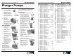
Figure 21
Figure 22
Figure 23
Figure 30
Figure 29
Figure 27
Figure 32
Figure 31
Figure 28
Figure 26
Figure 25
Figure 24
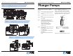
Service Pumps (continued)
(NOTE: This is done
to free the retainer
O-ring which is stuck
to the manifold) and
lift out. (See Figure
20 & 21)
5. With your fi ngers
pull the high pressure
seal and head ring
out of the head. (See
Figure 22)
6. The low-pressure seal
is located in the brass
seal retainer. Using
the mechanics
pick go in
between the
seal and retainer,
twist and pull, the
seal will come out
of the gland. (See
Figure 23 & 24)
7. Remove the seal
retainer O-ring with
the mechanics pick. (See
Figure 25)
Assembly:
1. Install the plastic
head ring into the
head (the fl at side is
on the bottom). (See
Figure 26)
2. Install the high-
pressure seal. Place
the seal so the open
“V” portion is toward
the head ring. You
need to place the
seal at an angle and
pull and push to
work the seal into
position with your
fi ngers (do not use
and tools you may
damage the seal).
Make sure the seal is
totally seated
against the head
ring. (See Figure
27 & 28)
3. Installing the
low-pressure seal.
You want the open
side of the seal to
be pointed toward
the water side of
the head (toward the
high-pressure seal) and
the fl at side toward the
drive end of the pump.
Place the seal into the
gland at an angle, with
your fi nger push the
exposed side of the
seal towards the center
and work the seal (See
Figure 29, 30 & 31) into
position. After the seal
is in the gland you can
work it into it proper
position.
4. Install the retainer O-ring.
(See Figure 32)