
Use and Care Manual


First Choice When Quality Matters
NORTH
AMERICA
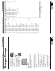
Plunger Pumps
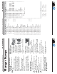
Operating Instructions and Parts Manual RC Series Pumps
RCA
1750 RPM
Repair Kits
3(6)
30(3)
12(3)
Water Seals
Kit 42469
Valves
Kit 2186
Pistons
Kit 42467
16(3)
14(3)
15(3)
4
5
6
7
8
1
2
11
19
20
21
22
23
24
25
12
13
14
16
28
29
30
34
3
10
27
9
1
2
3
15
17
18
26
31
32
33
35
36
37
39
40
41
38
42
44
43
20
45
46
47
48
43
20
44
45
77
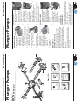
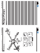
TYPE F8
78
Oil Seals
Kit 42468 (N)
Kit 42474 (E)
O-Rings
Kit 42470
2
(6)
7(1)
9(1)
16(3)
37(1)
39(1)
22(1)
33(1)
32(3)
45
Support Ring
Kit 2745
11(3)
Plunger Pumps
Operating Instructions and Parts Manual RC Series Pumps
First Choice When Quality Matters
NORTH
AMERICA
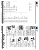
5. Install the retainer O-ring.
6. Squarely seat
the retainer
into the head
and push with
even pressure
until it snaps into
position. (See
Figure 25)
SERVICING THE PLUNGERS
If the plungers are not damaged they
do not need any servicing.
Tools required: 13mm socket, ratchet,
mechanics pick, taper blade gasket
scraper, thread sealant and torque
wrench.
NOTE: Be very careful when working
with the plungers, they are made from
ceramic which is brittle and can be
damaged.
Any time you remove a plunger it is
recommended you replace the slinger
washer, O-ring and top plunger washer.
The washers are a cushion for the
ceramic plunger and compress when
fi rst used and the O-ring will take a
set to create a seal and usually will not
spring back to its original shape. By not
replacing these parts you run the risk of
breaking a plunger or having a water
leak.
DISASSEMBLY
1. Remove the plunger
retainer nut. (See Figure
26)
2. Insert the gasket scraper
between the copper
washer and plunger to
remove the washer. (See
Figure 27)
3. Twist and pull the
plunger off the plunger
rod. (See Figure 28)
4. Remove the plunger
rod O-ring seal with
the mechanics pick.
5. Remove the brass slinger. At this
point clean any thread locker that
is left on the plunger rod and
retaining nut threads.
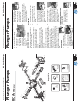
ASSEMBLY
1. Install the brass slinger washer.
2. Install the plunger rod O-ring.
Place a light fi lm of oil on the
O-ring.
3. Install the plunger by
pushing straight down
and twisting slightly in
either direction. Make
sure you fully seat the
plunger. (See Figure
29)
4. Install the small copper
washer on top of the
plunger and place a small
quantity of thread sealant
in the thread. Install the
plunger nut and tighten to
the required torque. (See
Figure 30)
(See Table D or
parts breakdown)
PUMP HEAD TO DRIVE END
INSTALLATION
1. Turn the crankshaft to
align the plungers as
shown. (See Figure 31)
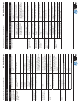
Service Pumps (continued)
Figure 25
g
g
g
g
g
g
g
Figure 26
Figure 27
Figure 29
Figure 30
Figure 31
Figure 28