
Use and Care Manual


First Choice When Quality Matters
NORTH
AMERICA
Plunger Pumps
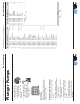
Operating Instructions and Parts Manual RC Series Pumps
RCV
3400 RPM
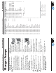
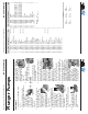
Repair Kits
3(6)
30(3)
12(3)
Water Seals
Kit 42476
Valves
Kit 2186
Pistons
Kit 42467
16(3)
14(3)
15(3)
4
5
6
7
8
1
2
11
19
20
21
22
23
24
25
12
13
14
16
28
29
30
34
3
10
27
9
1
2
3
15
17
18
26
31
32
33
35
36
37
39
40
41
38
43
20
44
45
77
46
47
48
TYPE F8
78
43
20
44
45
77
TYPE F7
78
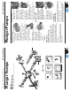
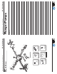
Oil Seals
Kit 42474
O-Rings
Kit 42470
2
(6)
7(1)
9(1)
16(3)
37(1)
39(1)
22(1)
33(1)
32(3)
45
Support Ring
Kit 2745
11(3)
Plunger Pumps
Operating Instructions and Parts Manual RC Series Pumps
First Choice When Quality Matters
NORTH
AMERICA
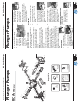
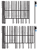
BELT DRIVE SYSTEMS
1. Mount the pump
securely to the
base plate. (See
Figure 10) For
new installation a
mounting rail kit is
required, refer to parts breakdown.
2. Install the pump pulley on the
crankshaft. It should be as far onto
the shaft as possible.
3. Align the pulleys so they
are in line. (See Figure
11)
4. Use a belt tension
gauge to assure proper
tension (too much
tension can cause
bearing failure or
damage the belts as
well as cause other
problems). (See
Figure 12)
5. Installation
complete.
Maintenance
SERVICING THE VALVES
The inlet and discharge valves in this
series pumps are all the same. The
valves are located under the six 21mm
hex plugs. The inlet valves are located
on the lower row and the discharge
valves are located on the top row of the
pump head.
Tools required: 21mm socket, ratchet,
needle nose pliers, mechanics pick and
torque wrench.
VALVE REMOVAL
1. Remove the valve cap.
(See Figure 13)
2. Inspect the valve cap
O-ring for any damage,
replace if necessary.
3. Use the needle nose
pliers to remove the
valve. (See Figure 14)
4. Use a small probe
to move the poppet
up and down to
assure that the valve is
functioning properly and that no
debris is stuck in the valve.
5. Inspect the valve seat o-ring for any
damage, replace if necessary.
VALVE ASSEMBLY
1. Insert the valve assembly
squarely into the port
push it squarely into
position with a small deep
well socket and extension
until fully seated. (See
Figure 15)
2. Install the valve cap
and torque to the
proper specifi cation.
(See Figure 16)
(See Table D or parts
breakdown)
SERVICING THE
PACKINGS/SEALS
To access the water seals for inspection or
replacement, you will fi rst need to remove
the head of the pump.
Tools required: 5mm hex socket, ratchet,
(2) long screwdrivers, reversible pliers,
mechanics pick and torque wrench.
Installation (continued)
Figure 10
Figure 12
Figure 11
Figure 13
Figure 14
Figure 16
Figure 15