
Use and Care Manual


First Choice When Quality Matters
NORTH
AMERICA
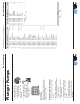
Plunger Pumps
Operating Instructions and Parts Manual RC Series Pumps
General Safety Information
(continued)
Maximum water temperature is
140°F.
All positive displacement plunger
pumps must have a safety relief valve
installed on the discharge side of the
pump, this valve could be either an
unloader or regulator and must be of
adequate fl ow and pressure for the
pump.
Adequate protective guards must
cover all moving parts. Perform
routine maintenance on the pump and
components.
Use only components that are rated
for the fl ow and pressure of the pump,
this would include hose, fi ttings, safety
valves, spray guns etc.
Electric Drive Pumps
Your power supply must conform to the
system requirements.
The motor must be grounded. Use
GFCI plugs and receivers.
Do not handle the pump/motor with
wet hands.
Only use power cords that are in
good condition.
Never pull the unit by the power
cord.
Never spray or clean the unit with water
Failure to follow these warnings
may result in personal injury or
damage to property.
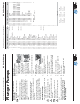
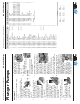
Installation
DIRECT DRIVE PUMPS
1. Install the shaft
key into the keyway
and apply a light
coating of anti-seize
on the engine shaft.
(See Figure 7 & 8)
2. Align the two key ways
and push the pump
completely onto the
engine.
3. Install all four (4) bolts and tighten
evenly.
4. Remove the red
shipping oil cap and
install the black
crankcase vent cap.
(See Figure 9)
5. Install the
appropriate unloader valve and
other accessories.
6. Install the appropriate water inlet
and discharge fi ttings.
7. Connect the water supply hose and
high-pressure discharge hose/spray
gun.
8. Turn on the water supply.
9. Open the spray gun to purge the
system of any air.
10. Start the engine.
11. Adjust the engine speed and
unloader valve.
Figure 9
Figure 7
Figure 8
Plunger Pumps
Operating Instructions and Parts Manual RC Series Pumps
First Choice When Quality Matters
NORTH
AMERICA
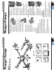
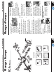
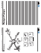
Legend
Pos. Code Description Qty. Pos. Code Description Qty.
1 3200110 Plug (216 in/lbs) 6
2 120690 O-Ring 6
3 2769050 Complete valve
(92 in/lbs) 6
4 800410 Screw 8
5 1381550 Washer 8
6 3200020 Head 1
7 180101 O-Ring 1
8 820361 Plug
(354 in/lbs) 1
9 740290 O-Ring 1
10 1980740 Plug (221 in/lbs) 1
11 1780140 Ring 3
12 1780720 Gasket 3
13 3200130 Piston guide 3
14 3200142 Gasket 3
15 3200260 Ring 3
16 770260 O-Ring 3
17 3200120 Piston guide 3
18 3200010 Pump body 1
19 1780490 Bearing 1
20 1260790 Snap ring 2
21 1780550 Snap ring 1
22 395081 O-Ring 1
23 3200090 Disc 1
24 3200080 Oil indicator 1
25 3200070 Cover 1
26 1200430 Screw
(92 in/lbs) 8
27 880130 Oil cap 1
28 1260110 Nut (106 in/lbs) 3
29 1260100 Washer 3
30 1260210 Piston guide 3
31 1260091 Spacer 3
32 1260460 Seal 3
33 480480 O-Ring 3
34 3200060 Piston guide 3
35 3200040 Conrod 3
36 1780050 Conrod pin 3
37 2760280 O-Ring 1
38 3200030 Rear cover 1
39 820510 O-Ring 1
40 880581 Plug 1
41 3200220 Screw 4
44 3201200 Crankshaft - Solid Shaft
1
44 3200860 Crankshaft - Solid Shaft 1
44 3201180 Crankshaft - Solid Shaft 1
44 3201170 Crankshaft - Hollow Shaft 1
44 3200350 Crankshaft - Hollow Shaft
1
44 3200340 Crankshaft - Hollow Shaft 1
42 3200330 Key 1
43 2760350 Bearing 1
45 480671 Seal 1
46 320210 Base 2
47 1322640 Washer 4
48 850250 Screw 4
77 1579 Flange (F7) 1
77 1584 Flange (F8) 1
78 1200430 Screw 4
AR64516 Oil 2
O
IL CAPACITY - 9.81 OZ
For For For
RCV2G25E RCV3G25E RCV2G25D
For For For
RCV25G27D RCV3G25D RCV35G25