
User manual

User Manual
Version 1.1
2013-09-09
RaspBee ZigBee addon board
www.dresden-elektronik.de
Page 8 of 21
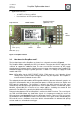
Via a service adapter footprint the JTAG signals of the built-in microcontroller are available.
In delivery state the adapter header is not assembled. See Section 10.1 for a custom
modification.
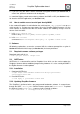
The 2.4 GHz radio module has two RF output traces. In default delivery state, only one RF
line is used which is routed to the assembled onboard chip antenna. Each firmware shall
ensure that the correct RF port gets selected. Although the chip antenna covers most of the
applications it is also possible to use an external antenna. This requires custom modifications
described in Section 10.2 as well as firmware changes.
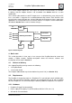
deRFmega256-23M12
JTAG
UART
VCC
4.5V to 5.5V
Reset
RFout 1
RFout 2
LDO
Vout
3.3V
LED1 LED2
Chip-Ant.
Coax-Conn.
GPIO
GPIO GPIO
Figure 2: Block Diagram
4. Quick start
This section describes in short steps a fast start-up of the RaspBee board to control and
monitor a ZigBee network. Detailed descriptions about the firmware, software and
functionality can be found in Section 5.
4.1. Content of delivery
One shipped RaspBee package contains the following:
1x RaspBee board
1x Instruction leaflet
The Raspbee addon board may also be obtained as part of a kit (see Section 15.3).
4.2. Requirements
The RaspBee is designed to work on a Raspberry Pi. In general both actual available types
of RPis will work with the RaspBee. However we recommend RPi type B, with assembled
Ethernet components. For full functionality the following additional components are required:
4.2.1. Hardware
Raspberry Pi (type B recommended)
Power supply for Raspberry Pi (AC/DC to Micro-USB, 5.0 V DC, min. 1 A)
SD card for OS and software