
User manual

User Manual
Version 1.1
2013-09-09
RaspBee ZigBee addon board
www.dresden-elektronik.de
Page 7 of 21
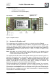
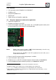
Application interfaces:
o 1x UART, 1x Reset, 1x GPIO
o User interface: 2x LED (red and green)
Figure 1: RaspBee in detail
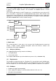
3.2. How does the RaspBee work?
The functional parts of the RaspBee are shown in a schematic overview in Figure 2.
The RaspBee will be supplied by the RPi 5.0 V domain. Therefore the AC/DC supply must be
sufficient to support the additional load. The most used AC/DC converters for RPi supply
enough power to compensate the slightly increased current consumption of the RaspBee. An
onboard low-drop-out voltage regulator generates a stable 3.3 V voltage to supply the radio
module and LEDs.
Note: All RaspBee signals (UART, RESET, GPIO, JTAG) work on a 3.3 V domain. A level
shifting of the signals to other voltage domains may be required if the RaspBee is
used on other base boards than the RPi.
The onboard placed radio module deRFmega256-23M12 by dresden elektronik contains an
8-bit AVR microcontroller with an integrated low-power 2.4 GHz transceiver for ZigBee and
IEEE 802.15.4 applications. The firmware is stored in the MCU internal flash and starts
automatically after the board gets powered on. Each RaspBee contains a world-wide unique
identifier, named MAC-ID. It consists of an 8 byte address, including the vendor ID and
product ID. The MAC-ID is stored in the MCU internal EEPROM.
Communication between RPi and RaspBee is realized via UART interface. The used signals
are TXD and RXD without any handshake signals. It is important to enable the access to
RPi’s serial port (see Section 4.4) to ensure the proper function. Two user LEDs (red, green)
are available to show RaspBee’s status. The low-active reset signal can be controlled by the
RPi and will cause a hardware reset of the built-in microcontroller. An onboard 10k pull-up
resistor avoids an unintended reset trigger.
Radio module
Service interface
(optional, n.a.)
LED2
LED1
LDO
RPi
socket
U.FL (n.a.)
Wire ant. (n.a.)
Chip antenna