
User manual

User Manual
Version 1.1
2013-09-09
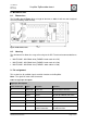
RaspBee ZigBee addon board
www.dresden-elektronik.de
Page 12 of 21
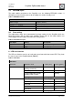
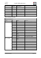
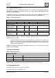
5.5. EEPROM layout
The radio module contained on the RaspBee uses the following EEPROM sections. If
developing custom firmware, please do not modify the sections already used.
Table 1: EEPROM sections
EEPROM sections
address range
content / remark
0x0000 ... 0x00FF
Bootloader specific
0x0100 ... 0x1EFF
user available
0x1F00 ... 0x1FDF
ZigBee firmware specific
0x1FE0 ... 0x1FFF
NV-section
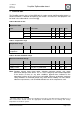
5.6. Fuse setting
The table below shows the recommended fuse byte settings for the RaspBee which the
board also comes with in factory new condition. Please refer to the radio module user
manual [4] for their description and alternative configurations.
Table 2: Extended fuse bytes
Fuse bytes
Setting
Description
EXTENDED
0xF8
Extended fuse byte
HIGH
0x90
Fuse high byte
LOW
0xCE
Fuse low byte
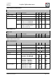
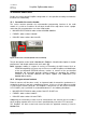
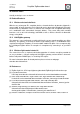
6. LED user interface
The LED user interface consists of a red and a green low-active low-current LED. They show
the actual status of the RaspBee board (Table 3).
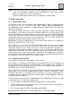
Table 3: LED status
LED status
Application
Application state
LED1 (red)
LED2 (green)
Bootloader
during initial 200 ms after start
(awaiting commands)
Off
Blinking
firmware update
Off
Blinking
no target application (invalid
Firmware/empty FLASH)
Off
Blinking
target application started
depending application
ZigBee firmware
Idle mode (TRX OFF)
Fast blinking
Off
Connecting
Slow blinking
Off
Connected
On
Off
Transmit
Off
On
Transmitted
Off
Off
custom firmware
n/a
depending application