User Manual RaspBeeTM Document Version V1.
User Manual Version 1.1 2013-09-09 RaspBee ZigBee addon board Table of contents 1. Overview ......................................................................................................................... 6 2. Applications ..................................................................................................................... 6 3. Features .......................................................................................................................... 6 3.1.
User Manual Version 1.1 2013-09-09 RaspBee ZigBee addon board 15. Related Products ........................................................................................................... 20 15.1. Wireless electronic ballasts .................................................................................. 20 15.2. LAN-ZigBee gateway............................................................................................ 20 15.3. Wireless light control starter kit ..................................
User Manual Version 1.1 2013-09-09 RaspBee ZigBee addon board Document history Date Version Description 2013-07-22 1.0 Initial version 2013-09-09 1.1 Update of radio certification section due to successful passed certification Availability of basic variant included www.dresden-elektronik.
User Manual Version 1.1 2013-09-09 RaspBee ZigBee addon board Abbreviations Abbreviation Description IEEE 802.15.4 Communication standard, applicable to low-rate Wireless Personal Area Networks (WPAN) CE Consumer Electronics ETSI European Telecommunications Standards Institute FCC Federal Communications Commission GPIO Generals Purpose Input Output JTAG Joint Test Action Group, digital interface for debugging of embedded devices, also known as IEEE 1149.
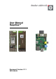
User Manual Version 1.1 2013-09-09 RaspBee ZigBee addon board 1. Overview The RaspBee™ is a ZigBee addon board for the Raspberry Pi (RPi). By using the RaspBee the Raspberry Pi becomes a full functional wireless node which can be seamlessly integrated into ZigBee networks. This will enhance the application range of RPi with monitoring and controlling ZigBee networks. ZigBee compatible devices are available from a lot of manufacturers.
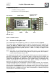
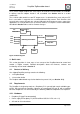
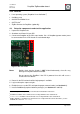
User Manual Version 1.1 2013-09-09 RaspBee ZigBee addon board Application interfaces: o 1x UART, 1x Reset, 1x GPIO o User interface: 2x LED (red and green) Chip antenna Service interface (optional, n.a.) Radio module RPi socket U.FL (n.a.) LED2 LED1 LDO Wire ant. (n.a.) Figure 1: RaspBee in detail 3.2. How does the RaspBee work? The functional parts of the RaspBee are shown in a schematic overview in Figure 2. The RaspBee will be supplied by the RPi 5.0 V domain.
User Manual Version 1.1 2013-09-09 RaspBee ZigBee addon board Via a service adapter footprint the JTAG signals of the built-in microcontroller are available. In delivery state the adapter header is not assembled. See Section 10.1 for a custom modification. The 2.4 GHz radio module has two RF output traces. In default delivery state, only one RF line is used which is routed to the assembled onboard chip antenna. Each firmware shall ensure that the correct RF port gets selected.
User Manual Version 1.1 2013-09-09 RaspBee ZigBee addon board 4.2.2. Software Linux operating system (Raspbian Linux distribution1) Qt4 library v4.8 deCONZ for ARMv6 Linux2 GCF Flasher3 ZigBee firmware for RaspBee4 (optionally) 4.3. Setup the components and start the application 1. Unpack the RaspBee unit. 2. Shutdown and Power-Off your RPi. 3. Connect the RaspBee to the RPi’s user header. Pin 1 of RaspBee (square marker) must be connected to Pin 2 of RPi header P1 at the board edge.
User Manual Version 1.1 2013-09-09 RaspBee ZigBee addon board 8. If you are using the “basic” variant, download the ZigBee firmware (see Section 5.2, in case of the “premium” variant this can be skipped). 9. Install the ZigBee control and monitoring software ‘deCONZ’ on RPi (see Section 5.3.1). 10. Start the deCONZ application (see Section 5.3.2). 4.4.
User Manual Version 1.1 2013-09-09 Notes: RaspBee ZigBee addon board GCFFlasher accepts firmware files in binary file format and in dresden elektronik’s proprietary GCF file format. There is no EEPROM programming support within GCFFlasher. EEPROM programming must be done within your application code. Please note that modifying the EEPROM may cause irreversibly damage to your RaspBee board. Use with care. GCFFlasher also provides the option ‘-r’ to reset the target device. 5.3.
User Manual Version 1.1 2013-09-09 5.5. RaspBee ZigBee addon board EEPROM layout The radio module contained on the RaspBee uses the following EEPROM sections. If developing custom firmware, please do not modify the sections already used. Table 1: EEPROM sections EEPROM sections address range 0x0000 ... 0x00FF 0x0100 ... 0x1EFF 0x1F00 ... 0x1FDF 0x1FE0 ... 0x1FFF 5.6.
User Manual Version 1.1 2013-09-09 RaspBee ZigBee addon board 7. Technical data The RaspBee contains the 2.4 GHz IEEE 802.15.4 radio module ‘deRFmega256-23M12’ by dresden elektronik. A detailed description of the module’s characteristics and properties can be found in the radio module user manual [4]. Table 4: Mechanical data Mechanical data Value Descriptor Parameter Size Min Typ Max Unit L 48.0 mm W 16.5 mm H 12.
User Manual Version 1.1 2013-09-09 RaspBee ZigBee addon board Table 7: Electrical characteristics Electrical characteristics Value Descriptor Parameter Min Typ Max Unit Supply voltage Vin 4.5 5.0 5.5 Output voltage Vout Supply current Iin_trxoff V 3.3 V Vin=5.0 V 15.8 mA Iin_txon Vin=5.0 V, TX_PWR=0x0 Vin=5.0 V, TX_PWR=0x6 Vin=5.0 V, TX_PWR=0xF 213.7 168.2 55.1 mA mA mA Iin_rxon Vin=5.0 V, Max. Sens. Vin=5.0 V, Reduced Sens. Vin=5.0 V, RPC On 32.0 31.7 26.
User Manual Version 1.1 2013-09-09 RaspBee ZigBee addon board 8. Mechanical size 8.1. Dimensions The RaspBee board (Figure 4) has a length of 48.0 mm, a width of 16.5 mm and a height of 12.0 mm (including socket for RPi). Figure 4: Mechanical size 8.2. Housing The slim board size allows the usage of housing for the RPi.
User Manual Version 1.1 2013-09-09 RaspBee ZigBee addon board 53 RFOUT2 Chip antenna 48 PF4/TCK JTAG Header not assembled 47 PF5/TMS JTAG Header not assembled 46 PF6/TDO JTAG Header not assembled 45 PF7/TDI JTAG Header not assembled - Vin Voltage supply 5 V supplied by RPi 2, 50 VCC Voltage supply 3.3 V generated internally 1, 31, 44, 49, 51 GND Ground System ground Table 11: Header pin description Header pin description Header Pin Signal Comment RPi socket 1 Vin 5.
User Manual Version 1.1 2013-09-09 RaspBee ZigBee addon board 10. Hardware modifications Besides the factory-default RaspBee configuration it is also possible to modify the hardware to enhance its functionality. 10.1. Assemble the service header The service interface provides the microcontroller programming interface of the radio module. It is useful to assemble a 50 mil 10-pin header on the top side to ensure a proper connection.
User Manual Version 1.1 2013-09-09 RaspBee ZigBee addon board Notes: The use of antenna types other than the listed approved antennas will cause in loss of the FCC certification. Regard the notes in Section 11.3 to work with a custom antenna in respect of CE and FCC requirements. The pre-installed ZigBee firmware does not support the 2nd antenna port. 11. Radio certification 11.1. United States (FCC) The RaspBee contains the radio module ‘deRFmega256-23M12’, which is certified according to FCC part 15.
User Manual Version 1.1 2013-09-09 RaspBee ZigBee addon board 11.3. Approved antenna list The RaspBee has an integrated chip antenna. The design is fully compliant with all regulations and certified as reference design of the radio module deRFmega256-23M12 (FCC-ID: XVV-MEGA23M12). As approved antenna(s) in connection with the coaxial connector (see Section 10.2) and a suitable U.
User Manual Version 1.1 2013-09-09 RaspBee ZigBee addon board 14. Revision notes Actually no design issues are known. 15. Related Products 15.1. Wireless electronic ballasts With the easy to integrate ZLL compliant wireless electronic ballasts by dresden elektronik a great number of lamps from the classic light bulb to the advanced multicolored LED matrix can be wirelessly controlled.
User Manual Version 1.1 2013-09-09 RaspBee ZigBee addon board dresden elektronik ingenieurtechnik gmbh Enno-Heidebroek-Straße 12 01237 Dresden GERMANY Phone +49 351 31850-0 Fax +49 351 31850-10 Email wireless@dresden-elektronik.de Trademarks and acknowledgements IEEE 802.15.4™ is a trademark of the Institute of Electrical and Electronics Engineers (IEEE). ZigBee is a registered trademark of the ZigBee Alliance. RaspBee™ is a registered trademark of the dresden elektronik ingenieurtechnik gmbh.