
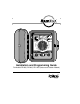
Manual


CAUTION: Do not connect the controller to one phase of a 3-phase power system
used by a pump or other electrical equipment.
Step 1 - Turn off the installation power source at
the associated circuit breaker. Verify that
power has been turned off by using an
appropriate AC voltage meter.
Step 2 - Install the conduit and associated fittings.
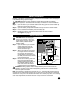
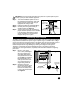
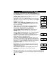
Step 3 - Connect power and ground wires per
electrical codes. See Figure 3.
Step 4 - Turn the power source on and check for
proper controller operation. If the controller
is not operating, disconnect the power
source and check for a short-circuit or
improper wiring in the system.
The built-in circuit protection in all Rain Dial controllers must have an earth ground path to
help protect the controller from power surges. A power surge is a sudden rise in voltage
on the main power line. A lightning strike on the power grid is the most common cause of
power surges and can be damaging to the controller. The built-in circuit protection
reduces the potential for surge damage by shunting the voltage to earth ground.
Therefore, an important step of the installation process is to properly connect the
controller to an earth ground source, especially if the controller is located in a lightning-
prone area.
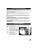
Step 1 - Route a 12-16 gauge
(2.0–1.0mm
2
) solid copper
wire in the shortest and
most direct path without
sharp bends from the earth
ground ( ) lug, located on
the terminal board, to an
earth ground source such
as a metal water pipe or
copper-clad ground rod.
Step 2 - Clamp the end of the
ground wire securely to the
pipe or ground rod. Make
sure the wire contact area
is free of dirt and corrosion.
See Figure 4.
7
Figure 3
Conduit
Body
Ground
(Green or
Green/Yellow)
Neutral Line
White or Blue
Hot Line
Black or Brown
Connecting Earth Ground
Figure 4
Copper-Clad
Ground Rod
Metal Water
Pipe
12-16 gauge
(2.0-1.0mm
2
)
Solid Copper Wire