
User Manual

*Pins PA6 and PA7 on the Orangutan X2 are connected by default through SMT jumpers to the a battery
voltage divider circuit and the user trimpot, respectively. You should not make external connections to these
pins without first breaking the default SMT jumper connections, which are located on the underside of the main
board and labeled in the silkscreen “ADC6=BATLEV” and “ADC7=TRIMPOT”.
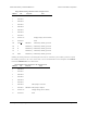
Differential Analog Channels on the Orangutan SVP and X2
Channel Positive Differential Input Negative Differential Input Gain
9 PA1/ADC1 PA0/ADC0 10x
11 PA1/ADC1 PA0/ADC0 200x
13 PA3/ADC3 PA2/ADC2 10x
15 PA3/ADC3 PA2/ADC2 200x
16 PA0/ADC0 PA1/ADC1 1x
18 PA2/ADC2 PA1/ADC1 1x
19 PA3/ADC3 PA1/ADC1 1x
20 PA4/ADC4 PA1/ADC1 1x
21 PA5/ADC5 PA1/ADC1 1x
22 PA6/ADC6 PA1/ADC1 1x
23 PA7/ADC7 PA1/ADC1 1x
24 PA0/ADC0 PA2/ADC2 1x
25 PA1/ADC1 PA2/ADC2 1x
27 PA3/ADC3 PA2/ADC2 1x
28 PA4/ADC4 PA2/ADC2 1x
29 PA5/ADC5 PA2/ADC2 1x
Pololu AVR Library Command Reference © 2001–2015 Pololu Corporation
2. Orangutan Analog-to-Digital Conversion Page 8 of 65