
Application Notes
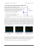
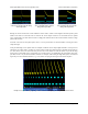
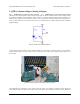
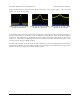
Table Of Contents
2. QTR-xA Sensor Output (Analog Voltages)
Each QTR-1A [http://www.pololu.com/catalog/product/958] and QTR-8A [http://www.pololu.com/catalog/product/960]
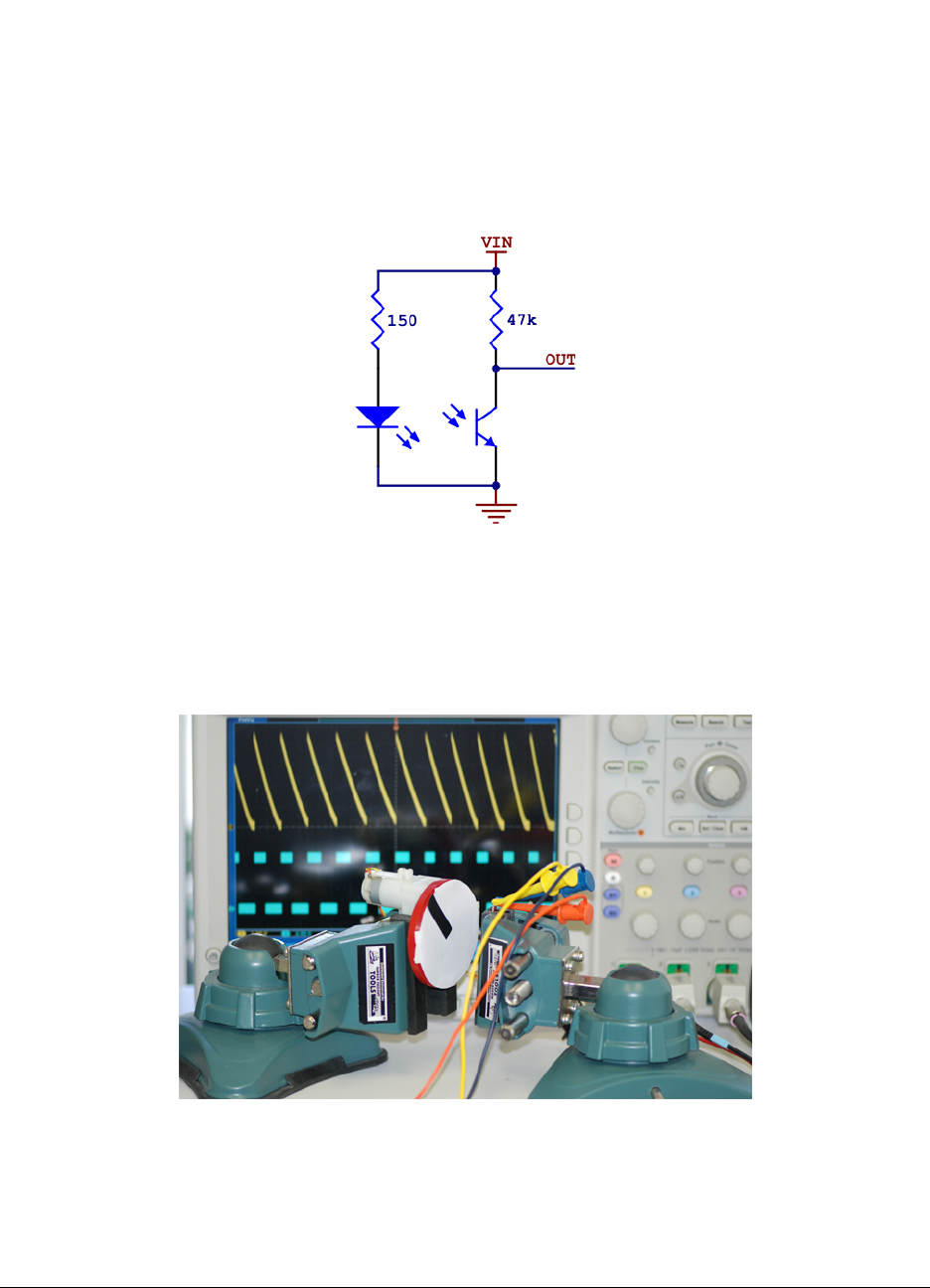
reflectance sensor phototransistor output is connected to a pull-up resistor as shown below to form a voltage divider
that produces an analog voltage output that ranges between 0 V and the supplied voltage (which is typically 5 V).
With a strong reflectance, such as when the sensor is over a white surface, its output voltage will tend towards 0 V;
with very weak reflectance, such as when the sensor is over a black surface, its output voltage will tend towards the
supplied voltage.
QTR-1A reflectance sensor schematic diagram.
To demonstrate what the QTR-xA sensor output looks like as it passes from a reflective surface to a non-reflective
surface and back again, we set up a motor to spin a white paper circle with a piece of black electrical tape on it as
shown below.
Experimental setup for QTR-1A and QTR-1RC oscilloscope outputs.
The following three oscilloscope screen captures show the output of the QTR-xA reflectance sensor during the
period where the black line passes by the sensor. The oscilloscope is set to 500 mV per division. The only difference
Pololu QTR Reflectance Sensor Application Note © 2001–2009 Pololu Corporation
2. QTR-xA Sensor Output (Analog Voltages) Page 4 of 5