
Application Notes
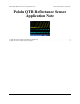
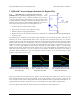
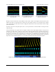
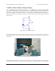
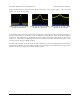
Table Of Contents
QTR-1RC output (yellow) when 3/8" above
a white surface and microcontroller timing
of that output (blue).
QTR-1RC output (yellow) when 3/8"
above a white/black interface and mcu
timing of that output (blue).
QTR-1RC output (yellow) when 3/8"
above a black line and microcontroller
timing of that output (blue).
Raising the sensor decreases the overall reflectance of the surface, which in turn lengthens all of the positive pulse
widths. This means we need more time to measure the sensor outputs and hence we are limited to lower update
rates. At this height, our white surface results in a high pulse width of 780 us and our black surface results in a high
pulse width of 10 ms.
Note that at the start of each yellow pulse, there is a 10 us period where our microcontroller is driving the sensor
output line high.
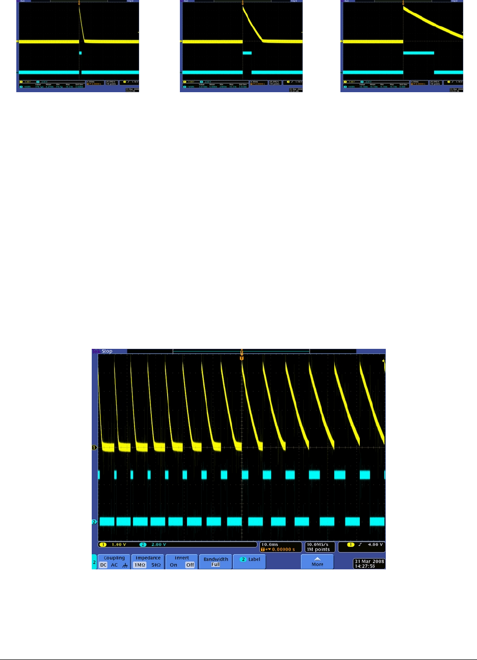
Lastly, the following screen capture shows an example of what the sensor output might look like as it sweeps across
a black line on a white surface. A motor was used to rotate a white paper disk with a piece of black electrical tape on
it in front of the sensor. The electrical noise present in the screen capture is from this motor. If you will be using
these sensors in electrically noisy environments (e.g. around motors), you should filter the signal either with a low-
pass filter circuit or in your microcontroller software. For example, when timing the high (blue) pulse, wait until the
signal stays low for a minimum duration (e.g. 10 us) before accepting the low signal as the end of the pulse.
Example series of QTR-1RC output signals generated as a black line on a spinning white disk passes in front of the sensor.
Pololu QTR Reflectance Sensor Application Note © 2001–2009 Pololu Corporation
1. QTR-xRC Sensor Output (Intended for Digital I/Os) Page 3 of 5