PIPE & WALL INSPECTION SYSTEMS ASSEMBLY AND OPERATING INSTRUCTION ---------------------------------------------------------------------------------------------------------- Read these instructions completely before operating this system 1
PLEASE CHARGE THE BATTERY FIRST BEFORE USE! Technical specifications camera Color camera with sapphire glass lens Wide viewing angle 120° Illumination 12 white LEDs Operating temperature -20°F ~ 120°F (-28°C ~ 50°C) Stainless steel house Stainless steel 304 PAL output 720X576(PAL) NTSC output 720X480(NTSC) Waterproof IP68 cable Special gold point touch connector to camera Fiberglass cable Cable length : 20□ 30□ meter monitor 7” TFT COLOR monitor OSD display Video output Picture Resolution:320 (TV Lines)
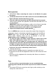
Save this Manual Attention 1. Read the this manual carefully before using this system. 2. Avoid using the device in extremely cold, heat, or humidity environment, it may damage the device. 3. Do not drop or press hard on the device. 4. Warranty invalidation if the device is disconnected by users or has any physical damages. 5. Always back up your date before connecting your SD device to this system. The manufacturer is not responsible for any date damage on your device for any reason. 6.
Know Your Tool ISOMETRIC VIEW 4
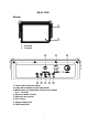
BACK VIEW Monitor 1. sunshade 2. 7’’monitor 1. Video1 video2 selector button 2. Image UP and down left and right button 3. Menu button (include bright contrast color langue 16:9 4:3 sleep) 4. Sub menu down selector 5. Sub menu up selector 6. Fuse socket 7. Charge adaptor jack 8.
Control part 1.Switch 2. led bright adjust knob 3.
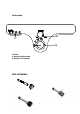
Basic operation 1. IMPORTANT: When connecting the camera to the Monitor the power must be off . 2. Screw the camera to the reel cable connect the reel to the Monitor (See Figure 1-B).make sure the camera lens is clean. 3. Press the switch on the monitor and DVR will work after five seconds. Gently insert the camera into a pipe duct, etc and reel out the cable until it is at the desired depth. IMPORTANT: Avoid kinking the fiberglass cable as this will cause irreversible damage.
• Turn the fuse cap counter clockwise to remove it from the battery box. • Only replace the fuse with a new one with the same specifications as the original one (F2A250V). Charge the battery 1) If the status LEDS on the battery box in lower level, charge the battery. Insert the charge adaptor cord into the battery charge jack.( Figure 2) 2) Switch to the charge position on control box. 3) Charge LED will be red during charging and turn to green when finish charging (normally charging time 6-7 hours).
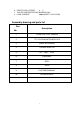
6. PROTECTIVE VOLTAGE 9 V 7. THE VOLTAGE BEFOR DISCHARGING 12.6V 8. LOAD CURRENT 600mA(INPUT 12.2V HOUR) Assembly drawing and parts list Part Description No.